 |
|||
|
|
|||
|
Page Title:
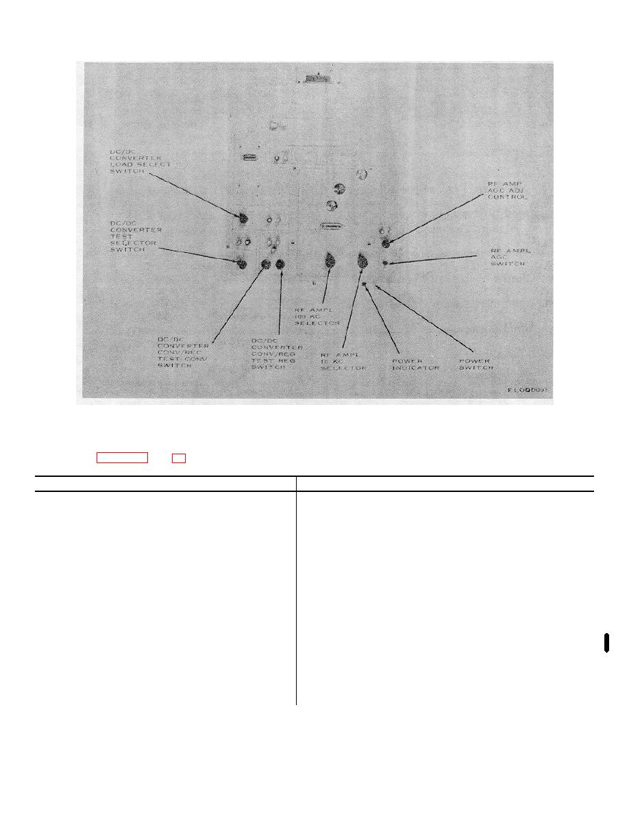
Common Module Tray A2, Controls, Indicators, and Connectors |
|
||
| ||||||||||
|
|  TM 11-6625-847-12
Figure 3-2 (2). Figure 3-2 (2). -- Continued
3-4.
Common Module Tray A2, Controls, Indicators, and Connectors
Control, indicator, or connector
Function
RCVR AUDIO S QUELCH SYNC switch ------------------
When set to ON, provides +27 volts dc to RCVR AUDIO
INPUTS SQUELCH SYNC test connection and connects
COMMON AUDIO 600 (ohm) IN connector to pin 6 of
connector J8 for receiver audio module, RT-662/GRC.
RCVR AUDIO SQUELCH switch ----------------------------
When set to OFF, provides ground to squelch circuit.
POWER switch---------------------------------------------------
Controls +27-volt dc primary power from test set SERV SEL
switch (positions SSB/NSK, FSK, AM and CW) to tray A2
circuits and connectors.
RCVR IF TEST SELECTOR switch-------------------------
Controls RCVR IF test points HI and LO for voltage
measurements of receiver if. module, AN/GRC-106.
Pos
Action
1
HI---Connected to ground
LO--Connected to 33 v d.
2
HI---Connected to man. RF gain.
LO--Connected to ground.
3
HI---Connected to BFO tune.
3
LO--Connected to ground.
Change 2 3-9
|
|
Privacy Statement - Press Release - Copyright Information. - Contact Us |
