 |
|||
|
|
|||
|
Page Title:
Figure 37. Coupler, Antenna CU-890/URM-85, schematic diagram. |
|
||
| ||||||||||
|
| 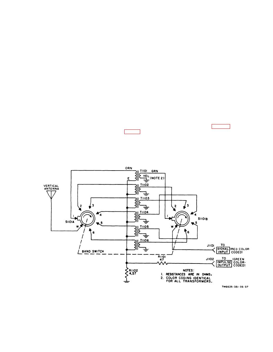 ( 1 ) above). The proper stepdown
shielded pickup loop at one end of a 9-inch
long probe, which is terminated in a mod-
r a t i o is obtained by rotating band
switch S1101 at the front of the
ified N -type connector at the opposite end
a n t e n n a housing to the same fre-
of the probe. Therefore, the loop is insen-
quency band in use by tuning unit 1.
i t i v e to the electric field component of
(2) Impulse generator signal path and
r a d i o interference signals, but is highly
to the - m a g n e t i c f i e l d
a t t e n u a t o r pad. When the vertical
responsive
a n t e n n a base with the five series-
component. Because of the reactively low
frequencies involved as compared with the
c o n n e c t e d mast sections is used,
c a l i b r a t i o n of the test set is ac-
frequencies encountered in tuning units 2,
complished in the same manner as
3, and 4, a number of turns of wire is re-
that described for the loop antenna
quired in the loop to induce an output signal
( a ( 2 ) above). The attenuator pad,
o f proper amplitude for driving the rf
which consists of R1101 and R1102,
a m p l i f i e r circuit in tuning unit 1. Con-
i s housed within connector J1102
nector plug P1301 delivers the signal
a n d provides 20-db of attenuation
power through the red color-coded coaxial
to the impulse generator cali-
c a b l e of Cable Assembly Set, Electrical
b r a t i n g signal. This attenuation is
MX-3410/URM-85 to the main unit front-
c o u n t e r b a l a n c e d as described in a
panel SIGNAL INPUT jack.
(3) above.
d. Coupler, Radio Frequency Interfer-
c. Probe, Magnetic Field, Interference
d u c t rf signals or noise interference sig-
To localize the magnietic field components
nals from 50-ohm impedance two-wire
of rf interference in the 150-kc to 30-mc
a u d i o - s i g n a l or electrical powerlines in
frequency range, a magnetic field probe is
t h e 150-kc to 30-mc frequency range, a
employed. This signal pickup device con-
capacitive-type pickup device is employed.
sists of a 3-inch diameter electrostatically
This coupler consists of a rectangular
Figure 37. Coupler, Antenna CU-890/URM-85, schematic diagram.
83
|
|
Privacy Statement - Press Release - Copyright Information. - Contact Us |
