 |
|||
|
|
|||
|
Page Title:
Figure 24. Tuning unit 2, mixer and oscillator (70-220 mc), schematic diagram. |
|
||
| ||||||||||
|
| 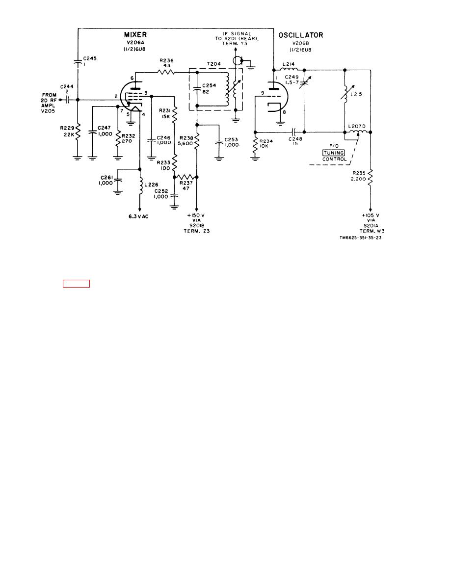 Figure 24. Tuning unit 2, mixer and oscillator (70-220 mc), schematic diagram.
39. If. Step Attenuator AT201
terminal 15 of multipin connector P201 (on
t h e rear of the tuning unit), feedthrough
c a p a c i t o r C2, a n d voltage-dropping re-
The output of either the 20-70-mc tuning
s i s t o r R7 to the coil of relay K2. With
section or the 70-220-mc tuning section is
r e l a y K2 energized, a 10-db T-pad (con-
coupled through wafer section Y of switch
s i s t i n g of resistors R3, R4, and R5) is
S201A (rear) and cable assembly W201 to
i n s e r t e d between the output of the mixer
input jack J1 on if. step attenuator AT201.
s t a g e and the input to interstage trans-
Relative steps of zero, 10 db, or 20 db of
former T205. The if. signal from the
attenuation are introduced into the circuit,
mixer has a path of continuity through the
depending on the position of the SIGNAL
m o v a b l e contact of relay K2 (energized)
ATTENUATOR DB control and switch S701,
and through the movable contact of relay
located in the main unit.
K1 (deenergized) to the 10-db T-pad. The
a. In the 0 SUBST. ONLY and 0 CW ONLY
output signal at connector J2 is, therefore,
p o s i t i o n s of SIGNAL ATTENUATOR DB
1 0 db smaller in amplitude than the cir-
s w i t c h S701, both relays K1 and K2 are
c u i t conditions present before energizing
d e e n e r g i z e d . Under this condition, the if.
relay K2.
signal at input connector J1 has a path of
c. In the 40-, 60-, and 80-db positions
continuity through the movable contact of
of SIGNAL ATTENUATOR DB switch S701,
r e l a y K2 direct to output connector J2.
the -150-volt supply line is coupled to two
Connector plug P211 and a short length of
terminals (14 and 15) of multipin connec-
coaxial cable feed the signal to the primary
tor P201 (on the tuning unit). Under this
o f transformer T205.
condition, - 1 5 0 volts dc is also applied
b. In the 20 DB position of SIGNAL AT-
through feedthrough capacitor C1 and
V o l t a g e - d r o p p i n g resistor R6 to energize
TENUATOR DB switch S701, the -150-volt
t h e coil of relay K1. With both relays
supply line has a path of continuity from
54
|
|
Privacy Statement - Press Release - Copyright Information. - Contact Us |
