 |
|||
|
|
|||
|
Page Title:
Figure 16. Tuning unit 1 rf oscillator, mixer, and oscillator, simplified schematic diagram. |
|
||
| ||||||||||
|
| 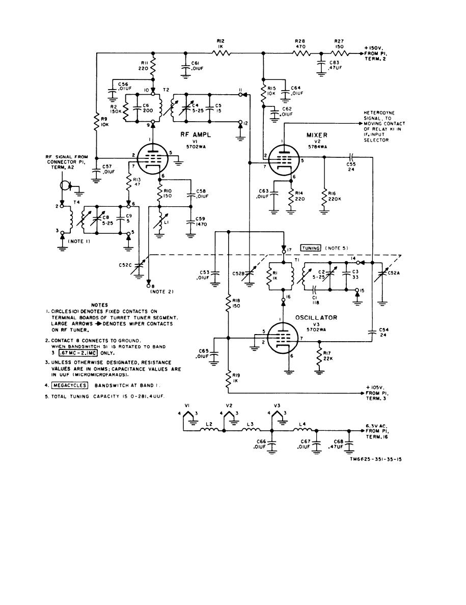 Figure 16. Tuning unit 1 rf oscillator, mixer, and oscillator, simplified schematic diagram.
must be used to assure that a 1,600-kc incoming rf
t h e rf section (and therefore the if. amplifier) at
signal does not saturate the 1,600-kc if. amplifier
the undesired incoming frequency of 1,600 kc. The
a n d thereby produce erroneous meter indications.
t u n e d circuit introduces a degenerative rf voltage
Tuned circuit L1 and C59 operate as an absorption
i n the cathode circuit of V1 at the 1,600-kc fre-
w a v e t r a p , drastically decreasing the response o f
quency.
38
|
|
Privacy Statement - Press Release - Copyright Information. - Contact Us |
