 |
|||
|
|
|||
|
Page Title:
Figure 3. Series method of calibration. |
|
||
| ||||||||||
|
| 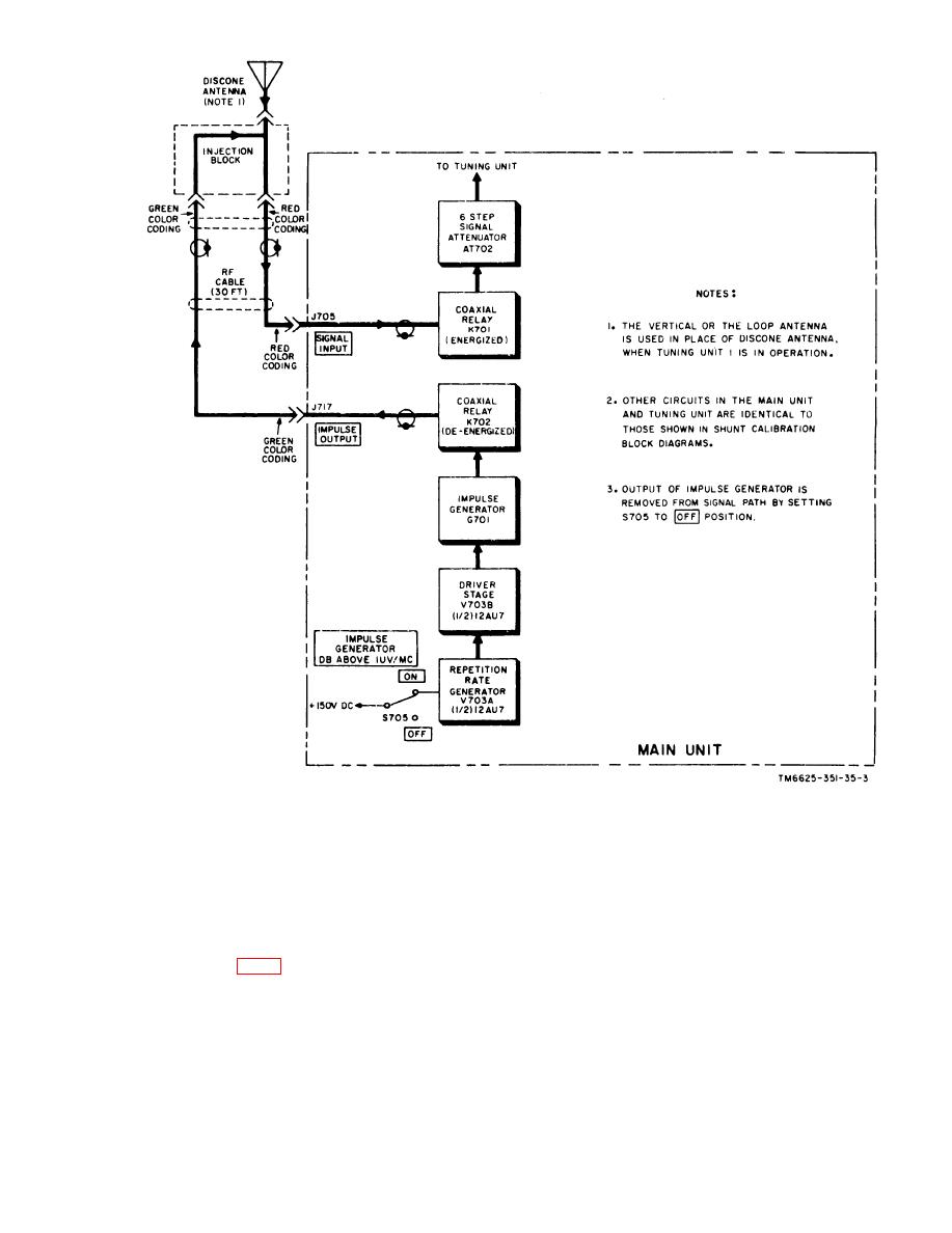 Figure 3. Series method of calibration.
r e a d i n g . For example: with the SIGNAL
be obtained with this test set by different
A T T E N U A T O R DB control at its 0 CW
basic methods of operation.
O N L Y position, the meter's decibles and
a. Direct Reading. One is the d i r e c t
microvolt scales are read directly, in-
reading method, in which the output of the
dicating 20-db above 1 microvolt full scale
s e l f - c o n t a i n e d impulse generator is ap-
(equivalent to 10 microvolt full scale). By
plied to the input circuit, while the incom-
the insertion of 20-db of attenuation in the
i n g rf signal is effectively removed from
s i g n a l path, the m e t e r calibration is
this circuit (fig. 1). The output controls of
c h a n g e d so that 40-db above 1 microvolt
t h e impluse generator are set to produce
a full-scale meter indication, with the
is now the full-scale indication (equivalent
t o 100 microvolt full scale). The test set
setting of the SIGNAL ATTENUATOR DB
c o n t r o l determining the full-scale meter
p r o v i d e s additional steps of attenuating
9
|
|
Privacy Statement - Press Release - Copyright Information. - Contact Us |
