 |
|||
|
|
|||
|
Page Title:
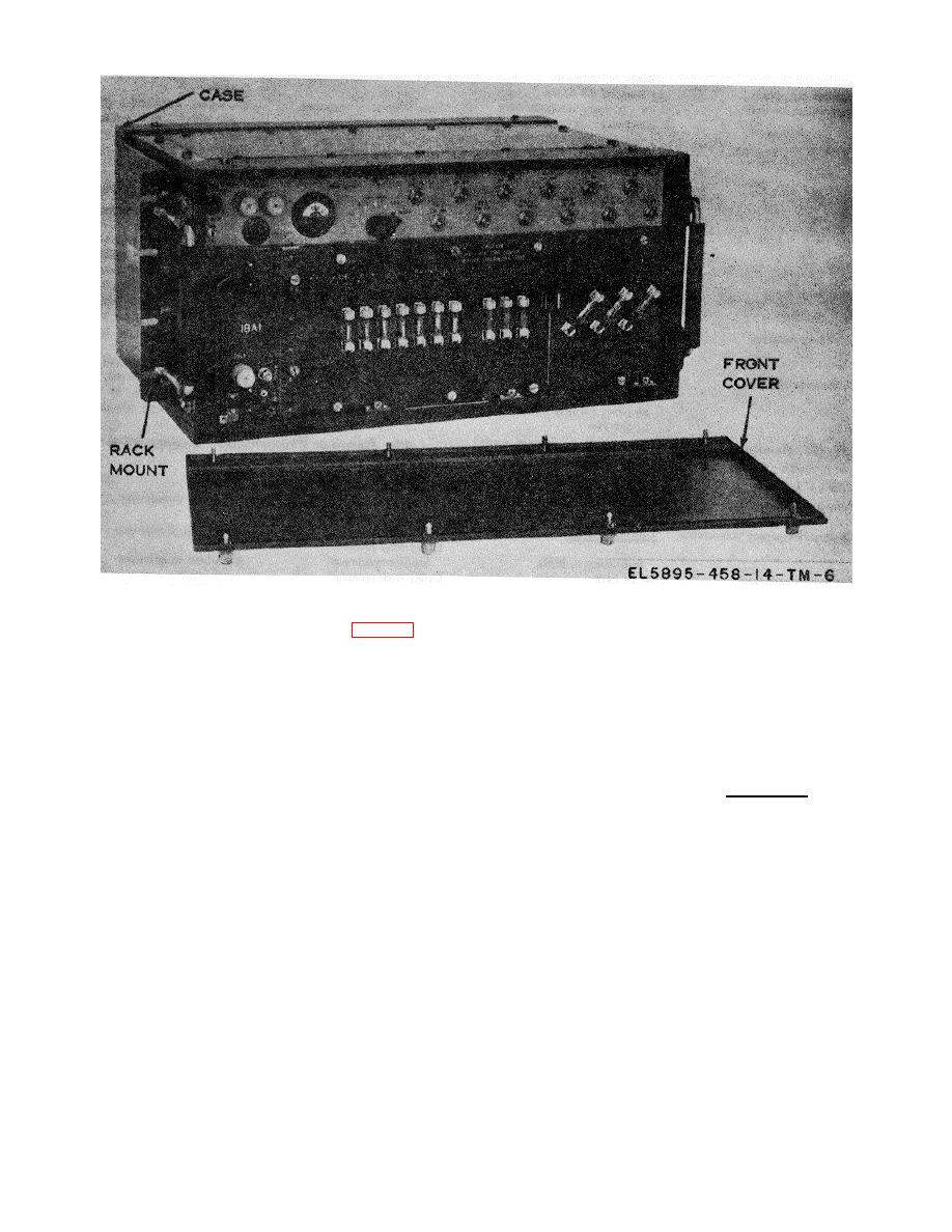
Figure 3-5. Converter, Telephone Signal CV-1548/G. |
|
||
| ||||||||||
|
|  TM 11-5895-458-14
Figure 3-5. Converter, Telephone Signal CV-1548/G.
(1) Transmitter, Radio T-983 (P)/ GRC- 103( V)
3-6. Radio Set AN/GRC-103(V)l
with Amplifier-Frequency Multiplier AM-4320/GRC-
a. Use . Radio Set AN/GRC-103(V)1 (fig. 3-6) is
103 (V).
a transportable radio set that provides facilities for
Frequency range:
multichannel radio transmissions and reception of
Band I
220.0 MHz to 404.5 MHz
pulse-code modulation (pcm) signals.
With
(channels 40-409).
appropriate plug-in transmitting and receiving units, the
Band II .................... 394.5 to 705.0 MHz
radio set operates in the frequency range of 220 to
(channels 389-1,010).
1,000 MHz in any one of 1,561 (RF) channels
Band III ................69.0 to 1000 MHz
selectable in 0.5 MHz increments. The radio set will
(channels 990-1,600).
accommodate up to 24 telephone channels when used
Channel/Frequency conversion Channel No. + 200 =
with the appropriate pcm multiplex equipment.
2
Configurations of Radio Set AN/GRC-103 (V) are the
...................................... frequency in MHz
AN/GRC-103 (V)1 (Band I), the AN/GRC- 103(V)2
Frequency accuracy...... ≠20 kHz
(Band II), and AN/GRC-103(V)3 (Band III). Operating
with its own antenna system Radio Set AN/GRC-103
Output power:
(V)(*) provides good performance over line-of-sight
Band I ..................25 watts minimum
paths in excess of 50 miles (80.45 kilometers) and has
Band II .................15watts minimum
sufficient reserve power to give satisfactory operation
Band III ................15 watts minimum
over obstructed paths. An order wire circuit, which
Output impedance......50 ohms, nominal, un
includes facilities that connect all stations of a system
balanced
on a party line basis, is provided for the use of
Modulation..................Frequency Modulation (FM)
Frequency deviation............ ≠300 kHz maximum
operating and maintenance personnel.
b. Technical Characteristics.
Output vswr ......................... 1.6:1 maximum
Deviation sensitivity............. 00 kHz to 400 kHz per volt
adjustable.
Input impedance, video ....... 91 ohms unbalanced
Input impedance, order
wire ............................... 600 ohms unbalanced
Frequency response....... .... Gaussian; -2.9 0.7
decibels (dB) at 500 kHz;
3-7
|
|
Privacy Statement - Press Release - Copyright Information. - Contact Us |
