|
| |
TM 11-5821-333-12
1-19. LOADING OPERATING DATA. Continued
A fill device is connected to the RT FILL connector using a fill cable. It contains lockout set
L875. It also contains hopset F234. The two must be loaded separately. The following de-
scribes lockout set loading.
Press the button LOAD (H-Ld). When pressed, this button lets the data go from the fill de-
vice to the holding memory (HM). The display shows LOAd. It then changes to HL875 and a
beep is heard. The H means lockout set L875 is in the HM. While the data is in HM, the display
shows HL875. It blinks every 7 seconds, A beep is heard with each blink.
Press the button STO (Sto/ENT), This lets the lockout set go into permanent memory (PM).
The display shows StoL8, blinks, and shows StoL8 again. A beep is heard when the display
blinks. The 800-series (L8) lockout set is now stored in the PM.
There is little difference between lockout set and hopset loading. When a hopset is being loaded and STO (Sto/
ENT) is pressed, the display shows Sto_.
The line on display means another keyboard entry is needed. The oper-
ator must tell the RT in which preset the hopset is to be stored. This is done by pressing a number button. The line
on display then changes to the preset number. The hopset is then in PM,
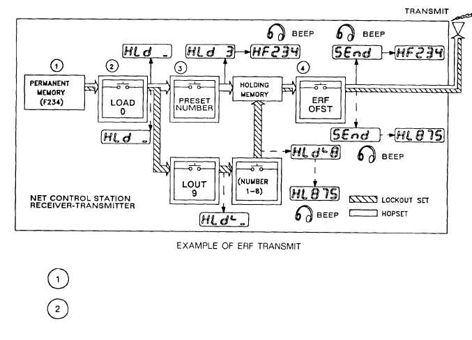
transmits lockout sets and hopsets to net member stations. The following drawings show what typically happens
during ERF. They show hopset and lockout set ERF. (The displays in the drawings are examples and the numbers
may differ from those seen during actual ERF. )
c. Recieve and Store Electronic Remote Fill (ERF). Using this method, the net control station (NCS)
The NCS RT PM has hopset F234 stored in it, It must be moved into the HM before it can be
sent (transmitted). This is called “ retrieve. ”
To retrieve a hopset, the NCS operator first presses button LOAD (H-Ld), The display
shows Hid_. The line on the display means another keyboard action is needed. The operator
must tell the PM in which preset F234 is stored.
1-15
|