 |
|||
|
|
|||
|
Page Title:
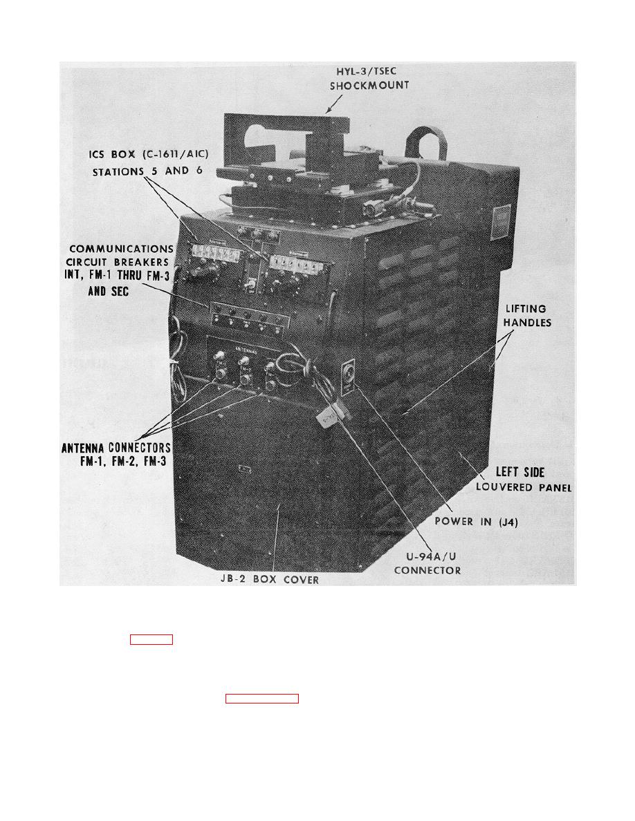
Figure 1-6. Console, Front and Left Side View. |
|
||
| ||||||||||
|
|  TM 11-5821-285-12-1
EL6QBOO6
Figure 1-6. Console, Front and Left Side View.
located in place of the station No. 3 C-7088/ARC-131
control head and the station 3 C-8157/ARC (KY-28)
assembly contains operator stations 1, 2 and 3; four
control head. The ARC-51BX control head may be
connectors U-94/U for stations 1 through 4, and the
installed in station 3 instead of the ARC-164 radio set. If
interphone junction box assembly JB-1. Each station
the ARC-51BX is installed, the console is configured for
contains an ICS box, an ARC-131 control head, and a
the (V)2 version only.
control head for the KY-28. As notes in paragraph 1-11,
the ARC-164 radio set may be
1-10
|
|
Privacy Statement - Press Release - Copyright Information. - Contact Us |
