 |
|||
|
|
|||
|
Page Title:
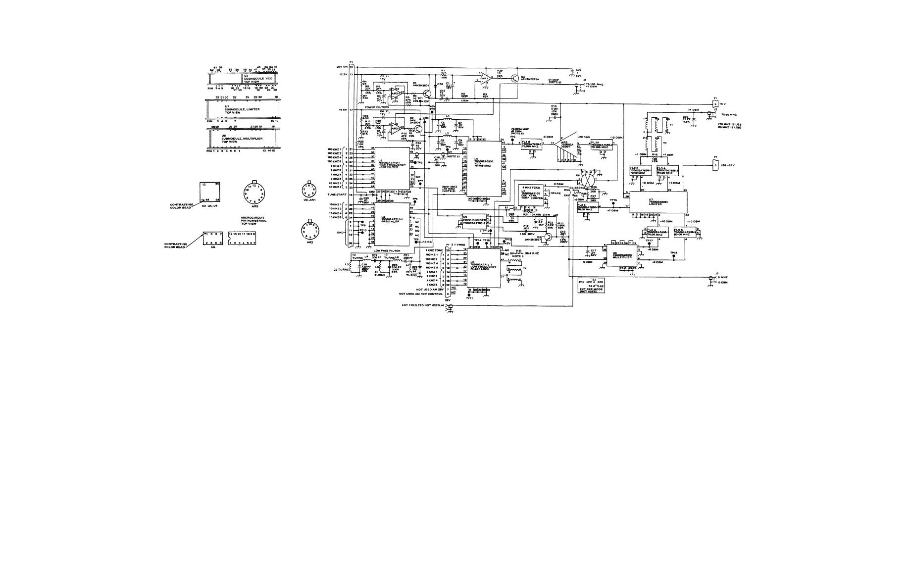
Figure 5-1. Synthesizer A1A3 Schematic |
|
||
| ||||||||||
|
|  TM 11-5820-919-40-2
NOTES: UNLESS OTHERWISE SPECIFIED
1. CAPACITANCE VALUES ARE IN MICROFARADS 10% l 00 V
2. RESISTANCE VALUES ARE IN OHMS 1/IIW
3. ALL DIODES ARE JAN1 N4148
4. FOR SIGNAL INPUT/OUTPUT ROUTING REFER TO FIGURE 2-1
5. PARTIAL REF DESIGNATION ARE SHOWN FOR COMPLETE DESIGNATION PREFIX WITH A1A3
6. VALUES SHOWN WITH FREQUENCY KHz SET TO 16005 4 (TEST POINT ACCEPTABLE RANGE 15+31VT087V)
Figure 5-1. Synthesizer A1A3 Schematic
47
|
|
Privacy Statement - Press Release - Copyright Information. - Contact Us |
