 |
|||
|
|
|||
|
Page Title:
Appendix III. DIPOLE ANTENNA KIT |
|
||
| ||||||||||
|
|  TM 11-5820-919-12
APPENDIX III
DIPOLE ANTENNA KIT
A3-1.
GENERAL
1. Decide on the direction that transmission is
required and determine the alignment of the antenna (fig
A3-2. This appendix provides information on the dipole
A3-7).
antenna kit and general instructions for setting up
various versions possible with this kit.
2. Unwind one of the dipole antenna reels to the
length specified in the antenna length table A3-1. The
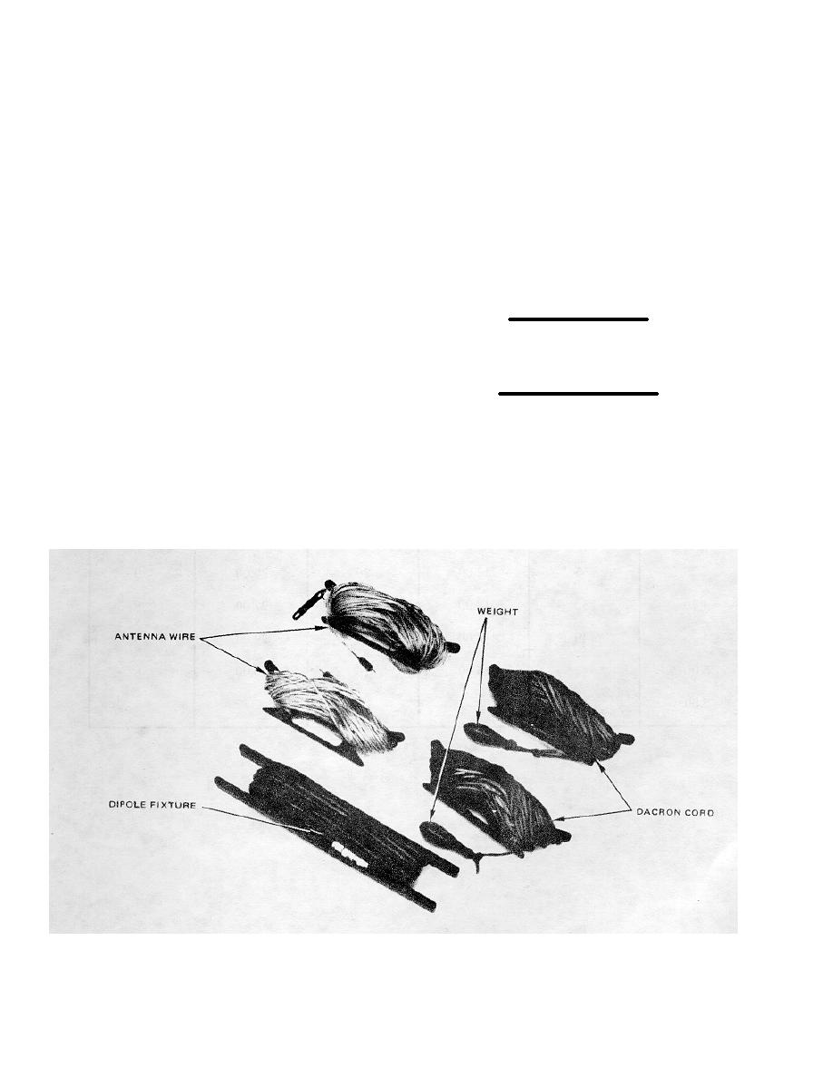
A3-3. The dipole antenna kit (fig A3-1) consists of two
equations for calculating dipole antenna lengths are:
reels of antenna wire with the required BNC plugs, two
reels of Dacron cord and weights, and a dipole lead-in
fixture. The components of the wire antenna kit can be
Each leg in feet
arranged in any of the following configurations: Slant
wire (fig A3-2), two-support dipole (fig A3-3), sloping
=
234
dipole (fig A3-4), or inverted-V dipole (fig A3-5). Figure
Frequency in MHz
A3-6 details the attachment of the antenna wires to the
dipole fixture.
Full length of dipole antenna in feet
A3-4. SLANT WIRE ANTENNA. A slant wire antenna is
=
468
much more effective than the whip antenna. The slant
Frequency in MHz
wire antenna requires the use of a dipole antenna (fig
A3-1) and an antenna support. It is used when greater
3. Loosen the antenna wire through the notch on
range is necessary than the whip antenna can provide,
the reel to present unwinding further and lay the reel
and when time or conditions do not allow the erection of
about 20 feet from the antenna support. Position the
a full horizontal dipole. The proper arrangement for a
radio set at the end of the antenna and insert the red
slant wire antenna is shown in figure A3-2. Erect a slant
plug of the antenna wire into the BNC connector of the
wire antenna as follows:
amplifier/coupler. Set ANT SEL switch to the BNC
(middle) position.
Figure A3-1. Dipole Antenna Kit
A3-1
|
|
Privacy Statement - Press Release - Copyright Information. - Contact Us |
