|
| |
TM 11-5820-890-30-5
6-1.
INTRODUCTION. Continued
All clocking signals are square waves with logic 0 and logic 1 levels. FSK frequencies are:
logic 1 = 2560 Hz.
logic 0 = 3200 Hz.
A description of each of the modules follows.
6-2.
CONTROL-MONITOR CHASSIS (7A1).
The control-monitor chassis includes the front panel, case, and backplane assembly (parent board). The front
panel has the operator controls and displays. The case has the connectors used to interconnect the
control-monitor to the other units in the system. The parent board provides the module interconnections. See
figure FO-17. Most of the test points used for troubleshooting are located on the parent board. See figure FO-18.
The display board requires two inputs from the microcontroller. DISPLAY DATA is a serial data stream that
controls the display. DISPLAY CLK is a 320-kHz clock signal that provides timing for the data. The front panel
switches are read by the decoder/timer.
6-3.
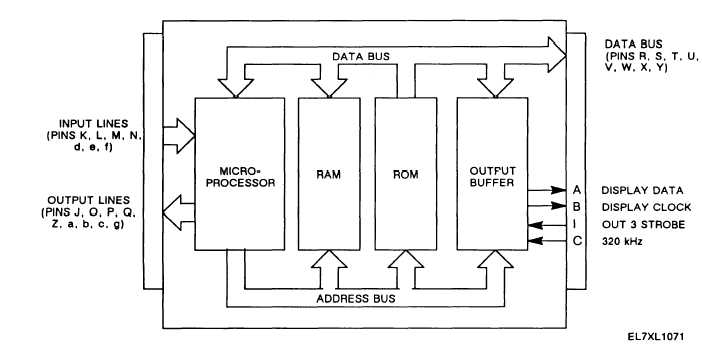
MICROCONTROLLER (7A2).
The microcontroller contains a microprocessor, memory, and interface circuits. It controls the operation of the
control-monitor by:
Generating control signals that operate I/O latches.
Monitoring and translating received data.
Generating data for transmission.
Monitoring the front panel switches.
Writing to front panel displays.
Figure 6-2 is a block diagram of the microcontroller.
Figure 6-2. Microcontroller Functional Block Diagram.
6-3
|