|
| |
TM 11-5820-890-30-5
4-17. REMOVAL AND INSTALLATION OF 5A3TB2 SHORTING BAR.
The 5A3TB2 shorting bar, which is only present on the AM-7239/VRC, must be removed prior to testing the
mounting adapter. It must be installed on the AM-7239/VRC prior to returning the mounting adapter to service.
Tools:
Cross tip screwdriver
Flat tip screwdriver
Torque screwdriver
ITEM
ACTION
REMARKS
a.
b.
c.
d.
e.
Mounting adapter
Six captive screws (1) on
rear access cover (2)
Rear access cover (2)
and seal
Shorting bar (3)
Rear access cover
(2), seal, and six captive
screws (1)
Set on its right side with bottom toward
you.
Using flat tip screwdriver, fully loosen six
captive screws (1) securing rear access
cover (2) on power control chassis.
Lift off of power control chassis.
Check its position. If it is properly install-
ed, skip to step e. Otherwise, using cross
tip screwdriver, remove and retain two
screws securing shorting bar (3) to termi-
nal block TB2. Remove and retain short-
ing bar for use after testing is completed.
Check seal. If damaged, replace rear ac-
cess cover (2). Otherwise, set it in place
and tighten six captive screws (1) secur-
ing it to power control chassis. Using
torque screwdriver, torque screws to 8
to 10 in-lb.
See figure 4-3.
For local operation, it
should connect 5A3TB2-1
to 5A3TB2-2. For remote
operation or testing, it
must not connect
5A3TB2-1 to 5A3TB2-2.
This was removed in
step c.
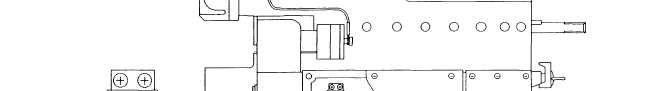
Figure 4-3. Shorting Bar Installation.
4-99
|