|
| |
TM 11-5820-890-30-5
2-8.
RECEIVE
SIGNAL PATH. Continued
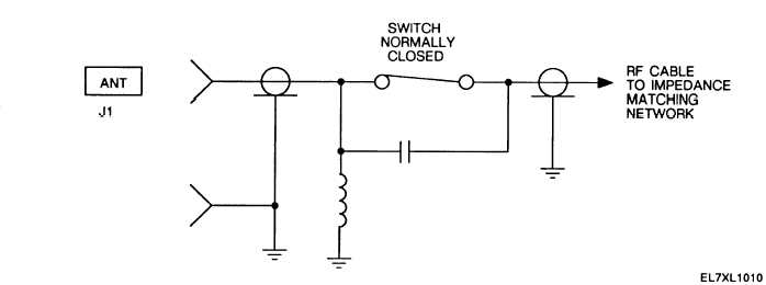
Figure 2-9. Antenna Connector Schematic
Keying and frequency selection are controlled by the control module. During receive, the T/R line is held at
logic 0. The operating frequency is distributed using the SERIAL DATA line. TUNE GATE-N and TUNE CLK are
used to decode the SERIAL DATA.
The RF signal from the impedance matching network goes to the exciter/power amplifier. After passing through a
low-pass filter, it is routed to the tuner/mixer. The tuner/mixer filters and amplifies the RF signal and then mixes it
with the local oscillator (LO) signal from the synthesizer. The LO is 12.5 MHz higher than the operating
frequency. The tuner/mixer and synthesizer are digitally tuned using the SERIAL DATA line. The 12.5 MHz IF
signal is routed to the lF/demodulator. The lF/demodulator demodulates the IF signal to recover the baseband
audio or data signal (FM DEMOD).
The SIG display is driven by the SIG STR RCV signal from the lF/demodulator. The SIG display should respond as
follows:
RF Level at ANT Connector
SIG Display
(dBm)
Segments Lit
-116 to -97
1
-108 to -87
2
-98 to -77
3
-88 to -67
4
-67 to -20
4 through 7 in sequence
The signal path is unchanged for FH operation. A SYNC CODE signal is recovered from the received signal and
used to synchronize the receiver with the transmitter. DATA SW-N, HOP TIME, and WB SEL are control lines from
the ECCM module used during FH operation. DATA SW-N is held at logic 1 during FH operation. HOP TIME goes to
logic 1 while the frequency is being changed. WB SEL (wideband select) goes to logic 0 when the RT looks for a
CUE signal. If a CUE signal is detected, the lF/demodulator sets the CUE PRESENT line to logic 1.
2-13
|