|
| |
TM 11-5820-890-20-2
1-32
1.12
RADIO ANALOG TRANSMIT PATH. Continued
b.
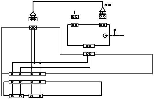
SINCGARS Radios Using the MX 10862/VRC (PSA).
J5
J4
J3
MOUNTING BASE
P1
J2
P1
HANDSET
POWER SUPPLY ADAPTER
C D
E N
C D
U
S
K
M
U
S
S
U
KEYING LINE
AUD/DATA
TRANSMIT LINE
RT OR RCU
RF
CABLE
TO ANTENNA
IF RT IS
PRESENT.
J1
TEST
CONNECTOR
AUD/FILL
E S
CX-13314/VRC
CABLE
NOTE:
THE ONLY LINE CONNECTED IN THE CX 13314/VRC IS P1,
PIN C TO P2, PIN E. THIS ALLOWS KEYING FROM AN
LS 671 OR AN/VIC 1 (V).
AUD/DATA AND AUD/FILL :
KEYING = PIN C
TRANSMIT = PIN D
P2
P1
The transmitter is keyed when the handset PTT switch is pressed. This places a ground on the handset
audio connector pin C. In the vehicular installation without an LS 671 or VIC, the handset is usually
connected to RT or RCU AUD/DATA connector. However, the handset may be connected to the
AUD/FILL connector if needed.
A PTT command can also be generated by the LS 671 or VIC.
Audio signals are also generated at the VIC or LS 671. Cables pass these signals to MB connector J3 or
J4, pin U. The audio also exits test connector J1, pin N, to aid in fault isolation.
|