 |
|||
|
|
|||
|
Page Title:
Section IV. PRINCIPLES OF OPERATION |
|
||
| ||||||||||
|
|  TM 11-5820-882-23/TM 06827A-23/2
All sealing surfaces (module cover and battery case)
always be used to stop the module travel and oppose the
prying force.
should have a thin film of silicone grease (NSN 6850-
c. Always inspect frame sockets for damage before
00-177-5094) applied to hepl preserve watertightness
inserting a module. .4 normal socket should have four
and keep the rubber seals pliable. If a handset is used
spring leafs visible. If a spring leaf is pushed over to the
with the radio set, a small amount of silicone grease
wrong side of a socket, it can be pushed back into place
should also be applied to the "O" ring in the connector
with a sharp pointed tool (pin, needle, scribe, etc.). If
to facilitate insertion.
the leaf breaks off or is smashed into the bottom of the
socket, the socket should be replaced if possible.
3-13. Placing in Service
However, the socket will still make good contack with
After the radio set has been repaired, the unit must be
the module pin after the damaged leaf is removed from
checked out completely with the minimum performance
the socket. The radio set is still operational until repairs
test (table 3-2). Upon the completion of the test, the
can be made at a higher level.
radio set should be set to some predetermined frequency
3-12. Lubrication
and properly aligned before being returned to service.
Section IV. PRINCIPLES OF OPERATION
3-16. Receive Operation
3-14. General
The receiver is packaged in three modules. These
Radio Set AN/PRC-68 consists of eight plug-in
modules are:
modules, a frame assembly, and battery assembly. Prin-
a. Converter Module (1A6). The converter
ciples of operation of the radio set is limited to descrip-
module consists of two bandswitched, varactor-tuned rf
tion of the modules and their interfacing with each
other. Refer to figures 2-1 and 2-2 for module loca-
amplifiers and the receiver 1st mixer which converts the
tions.
operating frequency to the first i-f of 12 MHz. The low-
band rf amplifier tunes the frequency range from 30 to
3-15. Circuit Functioning
54 MHz while the high-band tunes 54 to 80 MHz. The
settings of the frequency select switches (A, B, and D,
Circuit functioning of the radio set (fig. FO-1) can be
broken down into modules that comprise separate func-
on synthesizer module, and preset CHAN switch) deter-
tions (receive and transmit) and modules that are used
mine the operating frequency of the rf amplifier and the
for both functions (synthesizer and voltage controlled
local oscillator injection frequency to the first mixer.
oscillator). The battery saver circuitry, tone tuning, and
This injection signal is provided by the voltage controll-
150 Hz squelch tone signal are also discussed.
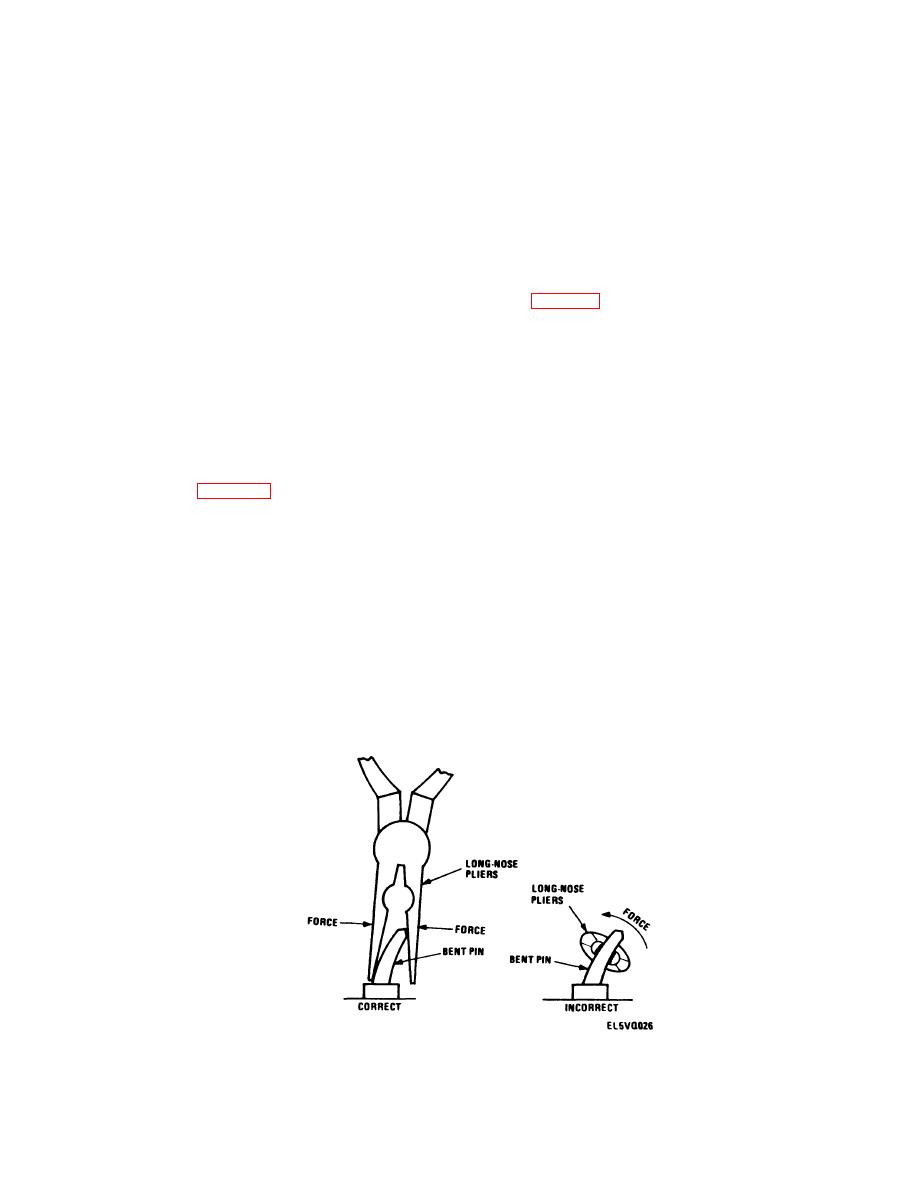
Figure 3-11. Pin Straightening procedure.
3-17
|
|
Privacy Statement - Press Release - Copyright Information. - Contact Us |
