 |
|||
|
|
|||
|
Page Title:
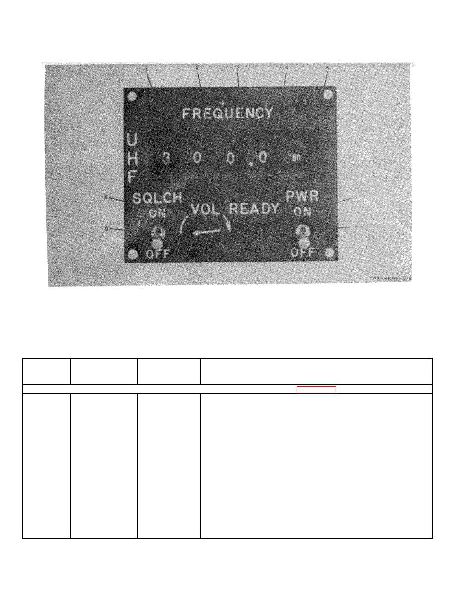
Figure 3-2. Radio Set Control C-7999/GRC-171 Controls and Indicators |
|
||
| ||||||||||
|
|  TO 31R2-2GRC171-2
TM 11-5820-815-14
NAVELEX 0967-LP-544-5010
Figure 3-2. Radio Set Control C-7999/GRC-171 Controls and Indicators
Table 3-1. AN/GRC-171 Controls and Indicators (Sheet 1 of 4)
CONTROL OR
REFERENCE
INDEX
INDICATOR
DESIGNATION
FUNCTION
RADIO RECEIVER-TRANSMITTER RT-980/GRC-171 (Figure 3-1)
1
TEST switch
A10A1S2
12-position rotary switch. Selects OFF or 1 of 9 inputs to
TEST meter as follows:
FWD PWR
REFLD PWR
% MOD
TEMP
+26V
+22V
+12V
+5V
-12V
2
TEST meter
A10A1M1
Multiscale meter. Presents visual indication of signals
selected by TEST switch S2 as follows:
(Cont)
FWD PWR and REFLD PWR on WATTS scale.
3-2
|
|
Privacy Statement - Press Release - Copyright Information. - Contact Us |
