 |
|||
|
|
|||
|
Page Title:
Repair of Digital Data Modem 1A12 |
|
||
| ||||||||||
|
|  TM 11-5820-695-35
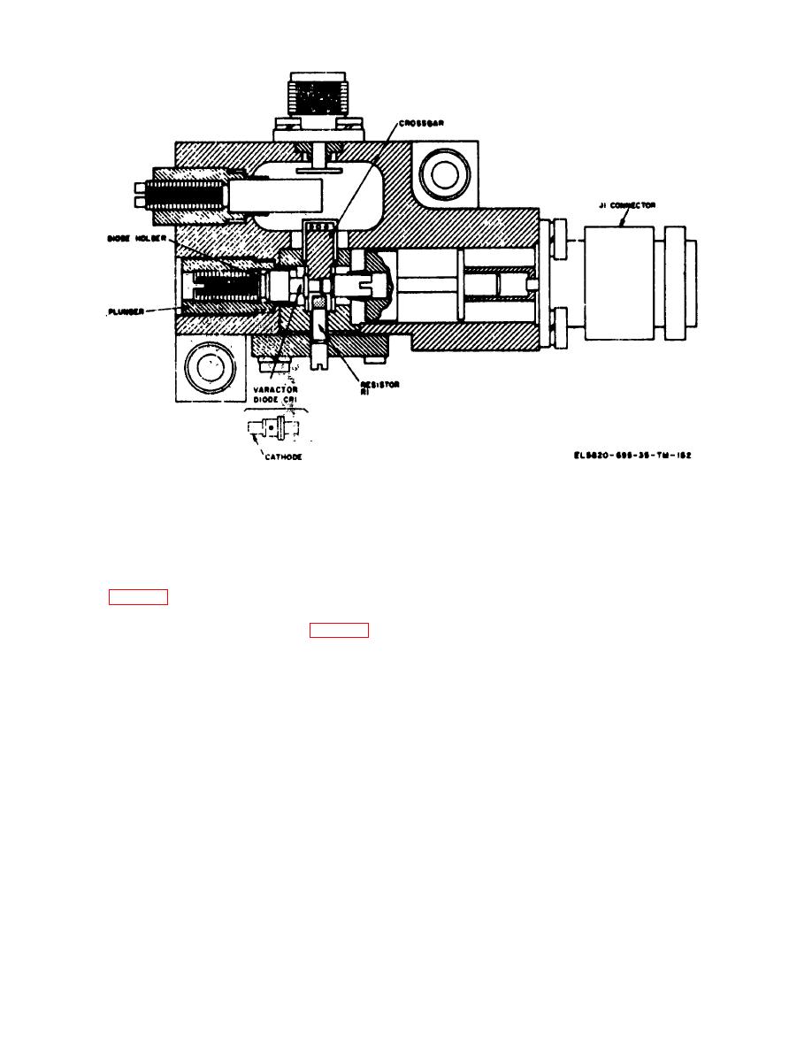
Figure 4-2. Transmitter 3rd stage frequency multiplier 1A10A2, varactor diode replacement.
(3) Replace inductor 1A11L26 and terminal lug
(2) Remove the 18 screws and washers
for resistor 1A11R22. Replace nuts, flat washers, and
securing heat sink on transmitter amplifier-frequency
lockwashers (removed in step a(3) above) on capacitors
multiplier 1A11 and remove the heat sink.
1A11C35 and 1A11C37. Do not tighten the nuts.
(3) Remove mounting nuts and lockwashers
from capacitors 1A11C35 and 1A11C37. Lift terminal lug
(4) Spacing between 1A11L26 and 1A11L27
for resistor 1A11R22 off 1A11C35.washer from capacitor
must be adjusted to 0.060 0.003 inch; spacing between
1A11C37 (fig. 5-74).
1A11L26 and 1A11L25 must be adjusted to 0.090 +0.003
inch. In each case edges of inductors must be parallel
(4) Remove rigid cable 1A11W5 connected
within 0.002 inch. Secure 1A11L26 in place by tightening
between connector 1A11J4 and 1A11J6 (B, fig. 5-74).
nuts on 1A11C35 and 1A11C37.
(5) Remove hex nut and spring lockwasher at
(5) Solder diode 1A11CR3 to inductor
opposite end of varactor diode 1A11CR3 (fig.4-3).
1A11L26.
Remove inductor 1A11L26 (meter bar) along with 1A
11CR3 soldered to it.
(6) Replace and secure top cover on
transmitter amplifier-frequency multiplier 1A11 using the
(6) Unsolder varactor diode 1A11CR3 from
26 screws and washers removed in a(1) above. Start with
1A11L26 and discard 1A11CR3. Remove excess solder
screws in center and work outward, Tighten screws to
from 1A11L26.
torque of 40-50 inch ounces.
b. Replacement of Varactor Diode 1A11CR3.
(7) Replace and secure heat sink to 1A11 using
(1) Install new varactor diode 1A11CR3 in
the 18 screws and washers removed in a(2) above.
place by fastening it securely to the chassis with hex-nut
4-7. Repair of Digital Data Modem 1A12
and spring lockwasher removed in step a(5).
a. General. Digital data modem IA12 contains II
(2) Replace rigid cable IAIIW5 removed in step
plug-in components replaceable at the organizational
a(4) above.
maintenance level (TM 11-5820-695-12) and digital
Change 5
4-4
|
|
Privacy Statement - Press Release - Copyright Information. - Contact Us |
