 |
|||
|
|
|||
|
Page Title:
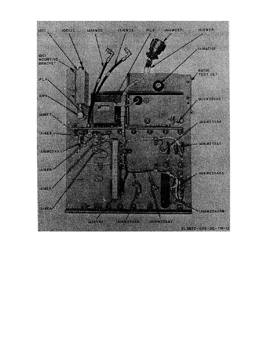
Figure 3-15. Plate assembly 1A16, rear view, parts location. |
|
||
| ||||||||||
|
|  TM 11-5820-695-35
Figure 3-15. Plate assembly 1A16, rear view, parts location.
the four screws securing the fan to the cabinet. Each
(8) Remove the fan from the cabinet.
screw has a synclamp nut which clamps the fan to the
cabinet frame.
b. Replacement.
(6) Tilt the fan upward to slide it past the
synclamps, then lower the fan into the cabinet
(1) Check that AIR FILOW arrow (printed on
(7) Tag the wires connected to the fan
side of replacement vane axial fan 1A15B1) is pointing
terminals. Remove the three screws that secure the
upward, and insert the fan into upper
wire lugs to the fan terminals. The lugs are soldered to
the tagged wires.
3-45
|
|
Privacy Statement - Press Release - Copyright Information. - Contact Us |
