 |
|||
|
|
|||
|
Page Title:
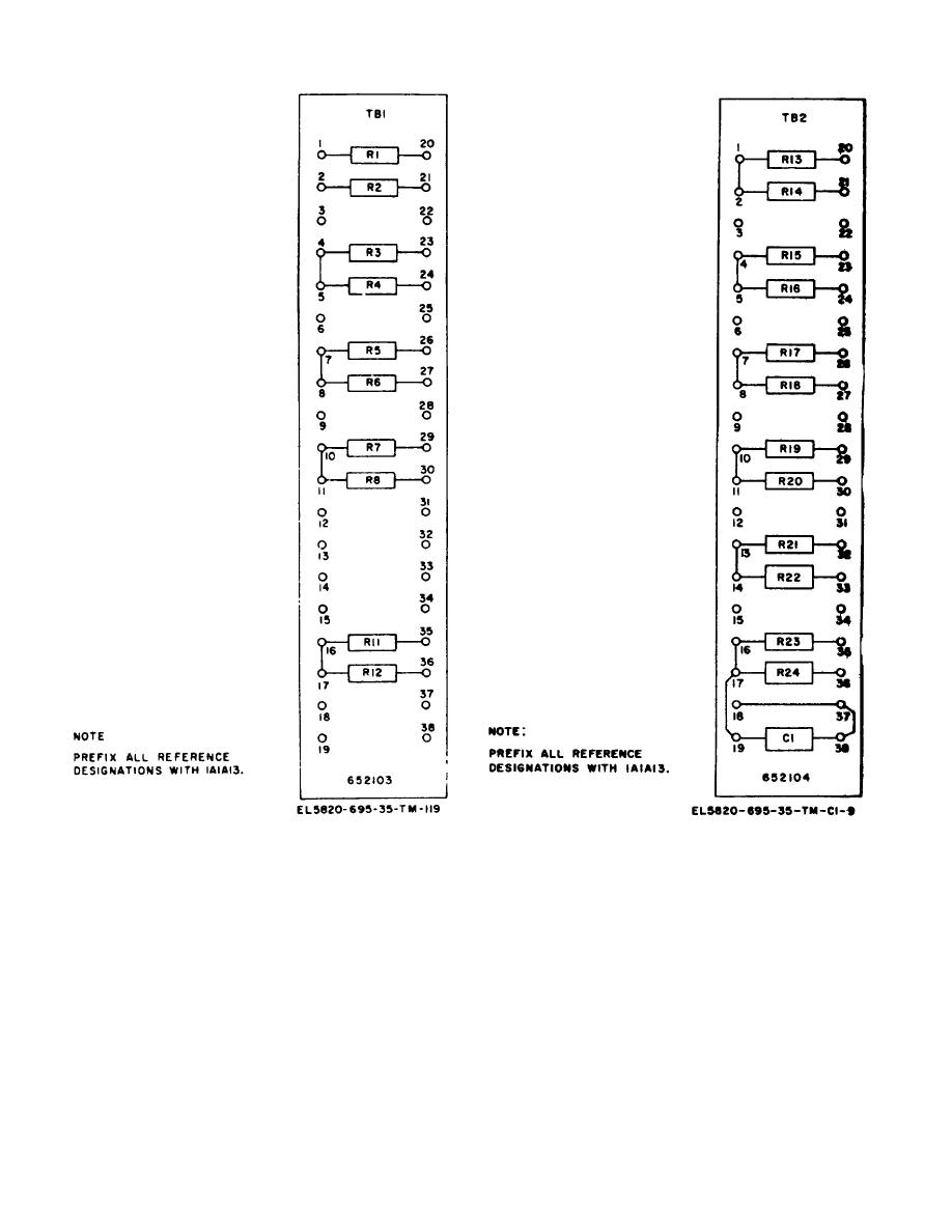
Figure 3-10. Terminal board 1A1A13TB1, top view, part location |
|
||
| ||||||||||
|
|  TM 11-5820-695-35
Figure 3-10. Terminal board 1A1A13TB1, top view,
Figure 3-11. Terminal board 1A1A113TB2, top view,
part location.
parts location
(2) If a connector contact requires
connector identical contact location. Refer to paragraph
replacement refer to the procedures provided in
3-37c for connector pin removal and replacement.
paragraph 3-37 for removal and replacement of
(6) Repeat step (5) for each wired connector
connector contact and proceed to step (7).
contact until transfer of all connector contacts is
(3) If the connector requires replacement,
completed.
remove the two screws, two nuts and washers recurring
(7) Mount and secure the bottom access
the connector and ground lug to power apply chassis
plate to power supply chassis assembly 1A1A13 using
assembly 1A1A13.
the 15 screws removed in step (1).
(4) Remove connector from mounting hole
g. Replacement of Power Supply 1A1.
and insert replacement connector in mounting hole.
(1) Insert 5/6v voltage regulator 1A1A1 into
Secure the replacement connector and ;round lug in
replacement power supply chassis 1A1A1;, aligning
position by tightening the two screws two nuts and
printed wiring board with guide rails located on upper
washers removed in step (3).
and lower portions of power
(5) Remove a wired connector contact from the
removed connector and install in the replaced
Change 1
3-41
|
|
Privacy Statement - Press Release - Copyright Information. - Contact Us |
