 |
|||
|
|
|||
|
Page Title:
Receiver Frequency Mixer Stage 2A8 Circuit Functioning |
|
||
| ||||||||||
|
|  TM 11-5820-695-35
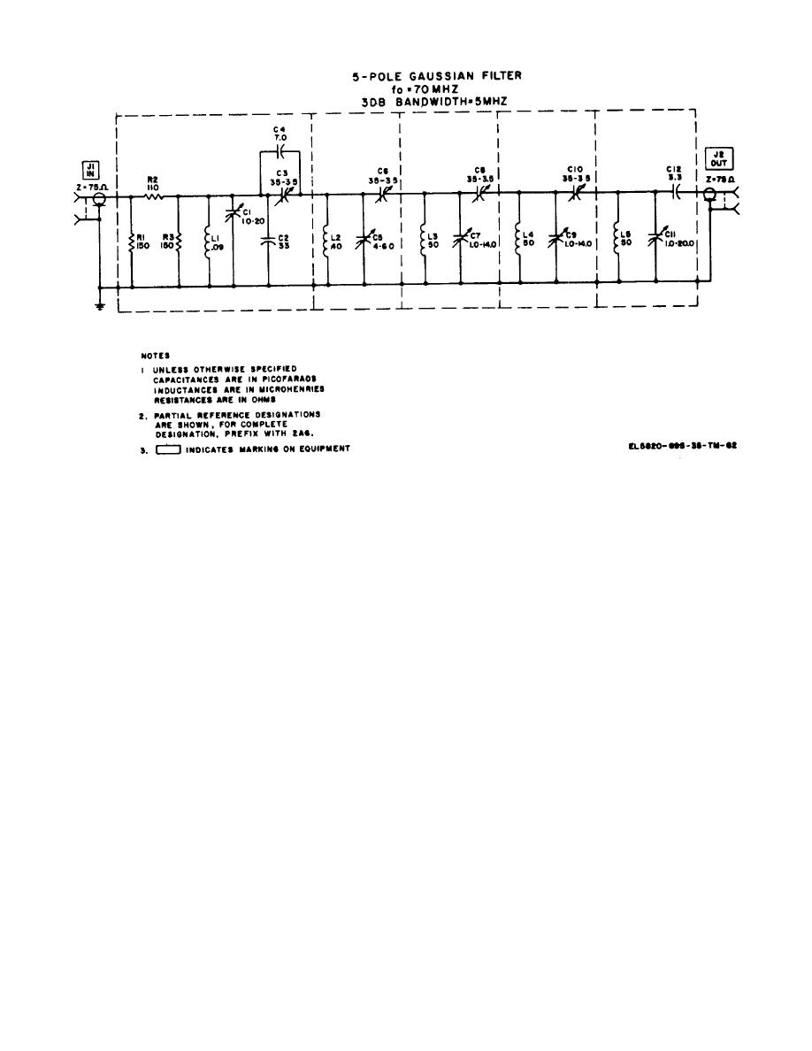
Figure 2-25. 70 MHz band pass filter (B=5.0 MHz) 2A6 (684447), schematic diagram.
stage Q2, and capacitor C16 is the if signal bypass for
RT1 and potentiometer R12. Thermistor RT1 also
2-72. Receiver Frequency Mixer Stage 2A8 Circuit
provides temperature compensation for the gain of this
Functioning (fig. S:6)
stage over a wide temperature range. Potentiometer
Receiver frequency mixer stage 2A8 produces the 4.33
R12 sets the operating current through second
to 5.07 GHz local oscillator signal by mixing the 220
preamplifier stage 02, and, therefore, sets the gain of
MHz signal from the 220 MHz frequency multiplier-osc
second preamplifier stage Q2.
2A13 with the 4.55 to 4.85 GHz signal from bandpass
filter 2FL21. Receiver frequency mixer stage 2A8
consists of 220 MHz bandpass filter FL1, crystal mixer
d. Third Preamplifier. Third preamplifier Q3 also
Z1, a crystal current metering circuit, and coaxial
amplifies the 70 MHz if signal. Its output is coupled by
circulator HY1.
C17 to 70 MHz bandpass filter 2A6 through output plug
P2 designated IF OUT. Resistors R17, R19, R20, and
a. 220 MHz Bandpass Filter 2A8FL1. 220 MHz
provide a 75 ohm output impedance. Capacitor C22 is
bandpass filter 2A8FL1 is a three-pole Chebyshev type
variable in this network to permit matching the load.
bandpass filter. Maximum insertion loss is 8 db;
Resistors R13 and R14 provide fixed dc bias for third
bandwidth is 11.5 MHz at the 3 db reference points.
preamplifier stage Q3, and inductor L9 is its collector
The input is filtered by 2A8FL1 for application to crystal
load.
Emitter resistor R15 provides negative ac
mixer 2A8Z1.
feedback to stabilize this stage, and capacitor C19 is the
ac bypass. Resistors R15 and R16 determine the
b. Crystal Mixer 2A8Z1. Crystal mixer 2A8Z1 is
current through third preamplifier stage Q3. The 70
similar to a conventional balanced coaxial mixer but
MHz if signal out of third preamplifier stage Q3 is also
uses two forward diodes CR1 and CR2. The unit
coupled by C18 to a diode detector circuit formed by
accepts a 220 MHz input signal at a level of +11 dbm to
CR3, R18, and C21. This provides a positive dc voltage
+13 dbm and an input signal in the frequency range
which is proportional to the level of the detected if signal
4550 to 4850 MHz at a level of + 16 dbm to +22 dbm.
at jack J4 designated TP1 IF MON. Test point TP1 IF
The resultant rf output
MON can be connected to the meter on meter panel
assembly 2A15A2 with a test lead.
2-114
Change 6
|
|
Privacy Statement - Press Release - Copyright Information. - Contact Us |
