 |
|||
|
|
|||
|
Page Title:
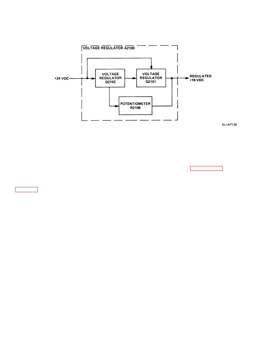
VOLTAGE REGULATOR ASSEMBLY A2100. |
|
||
| ||||||||||
|
|  TM 11-5820-670-30
1-56. VOLTAGE REGULATOR ASSEMBLY A2100.
Voltage regulator assembly A2100 provides a regulated output of +16 vdc for circuits in the receiver-
transmitter. The regulator maintains + 16 vdc output over a wide range of current demands.
Potentiometer R2106 adjusts biasing levels and the regulated output of +16 vdc, while +24 vdc biases
voltage regulators Q2102 and Q2101.
Voltage regulator assembly A2100 includes a time delay circuit which is discussed in paragraph 1-19.
1-57. POWER SUPPLY ASSEMBLY A9500.
Power supply assembly A9500 provides +24 vdc for radio set operation and provides 400 Hz voltage for
cooling fan motor operation during transmit mode. An unregulated 27.5 vdc output is also supplied by
the assembly.
COOLING FAN OPERATION
The cooling fan turns on when the radio set is operated in the transmit mode. The +24 vdc from the
series regulator is converted to 400 Hz by the dc-ac converter which is used to power the cooling fan.
When the push-to-talk button is pressed, a transmitter ground signal is applied to the dc-ac converter
causing the stage to oscillate at 400 Hz. The 400 Hz power level is coupled through transformer T9501
to motor B9501, which causes it to turn on.
1-60
|
|
Privacy Statement - Press Release - Copyright Information. - Contact Us |
