 |
|||
|
|
|||
|
|
|||
| ||||||||||
|
|  TM 11-5820-670-30
1-49. RF CONTROL ASSEMBLY P/O MODULE A4500 (TRANSMIT MODE). (CONT)
When the push-to-talk button is pressed, transmit/receive relay K4501 is energized, allowing
transmitted rf to flow to the sidetone gate detector and reflectometer from band-pass filter FL4501.
Rf signals entering the detector are rectified by diode CR4514 and applied to amplifier Q4501.
Amplifiers Q4501 and Q4502 will not conduct until 0.6 watt biases diode CR4514. When transmitted
power reaches 0.6 watt or higher, Q4501 and Q4502 conduct sending a ground signal (sidetone gate
signal) to relay K5501, energizing it. Energizing K5501 causes relay K5502 to apply the + 16 vdc to
audio amplifier A5400 for unsquelching.
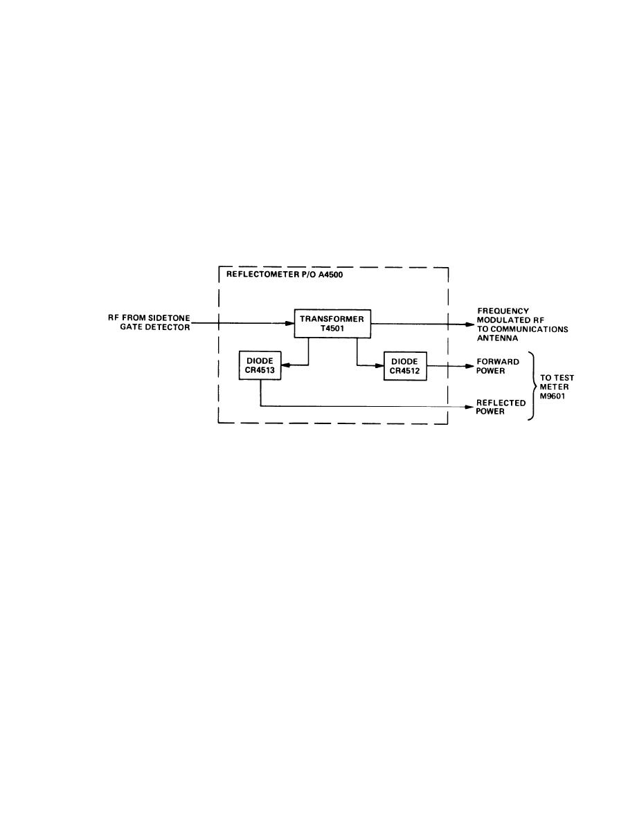
REFLECTOMETER
EL1AT123
Rf signals being applied to the sidetone gate detector are also applied to transformer T4501 in the
reflectometer. Rf is coupled through the primary of T4501 to the communications antenna and is
radiated.
The secondary of transformer T4501 couples a portion of the output power to diodes CR4513 and
CR4512. CR4513 detects reflected power and CR4512 detects forward power. In order for power to
reach the test meter from either diode, power being coupled from transformer T4501 to the diodes
must be at least 0.6 watt.
1-49
|
|
Privacy Statement - Press Release - Copyright Information. - Contact Us |
