 |
|||
|
|
|||
|
|
|||
| ||||||||||
|
|  TM 11-5820-670-30
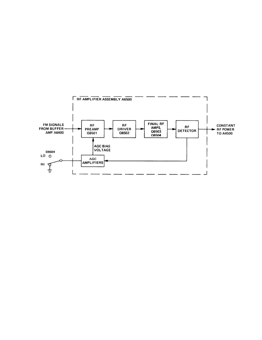
1-48. RF AMPLIFIER ASSEMBLY MODULE A6500. (CONT)
The rf detector is a directional coupler circuit that samples the forward and reflected power com-
ponents of the rf output signal. The voltages from the final rf amp stage are rectified by diodes CR6501
and CR6502 and applied to the agc amplifiers.
AGC AMPLIFIERS
EL1AT120
The rf and agc amplifiers form a feedback loop which ensure a constant level of rf output to module
A4500. The power output level desired for a specific application may be selected at the receiver-
transmitter front panel by setting XMTR HI-LO power switch S9604 to either of two positions. In the LO
position, the output level to A4500 is held to 1 watt. In the HI position, agc action is held to a minimum
and the output power is increased to 10 watts.
With switch S9604 in LO position, a larger signal is applied from the rf detector agc amplifiers. A
larger signal entering the agc amplifiers causes a decreased current level entering rf preamp Q6501.
Having a decreased current level, conduction of Q6501 decreases, holding the rf output to A4500 at 1
watt.
With switch S9604 in HI position, a reduced signal is applied to the agc amplifiers. A reduced signal
entering the agc amplifiers causes an increased current level to Q6501. Increased current causes
conduction of Q6501 to increase, bringing the rf output power to 10 watts.
1-47
|
|
Privacy Statement - Press Release - Copyright Information. - Contact Us |
