 |
|||
|
|
|||
|
Page Title:
MASTER OSCILLATOR MODULE A6300. |
|
||
| ||||||||||
|
|  TM 11-5820-670-30
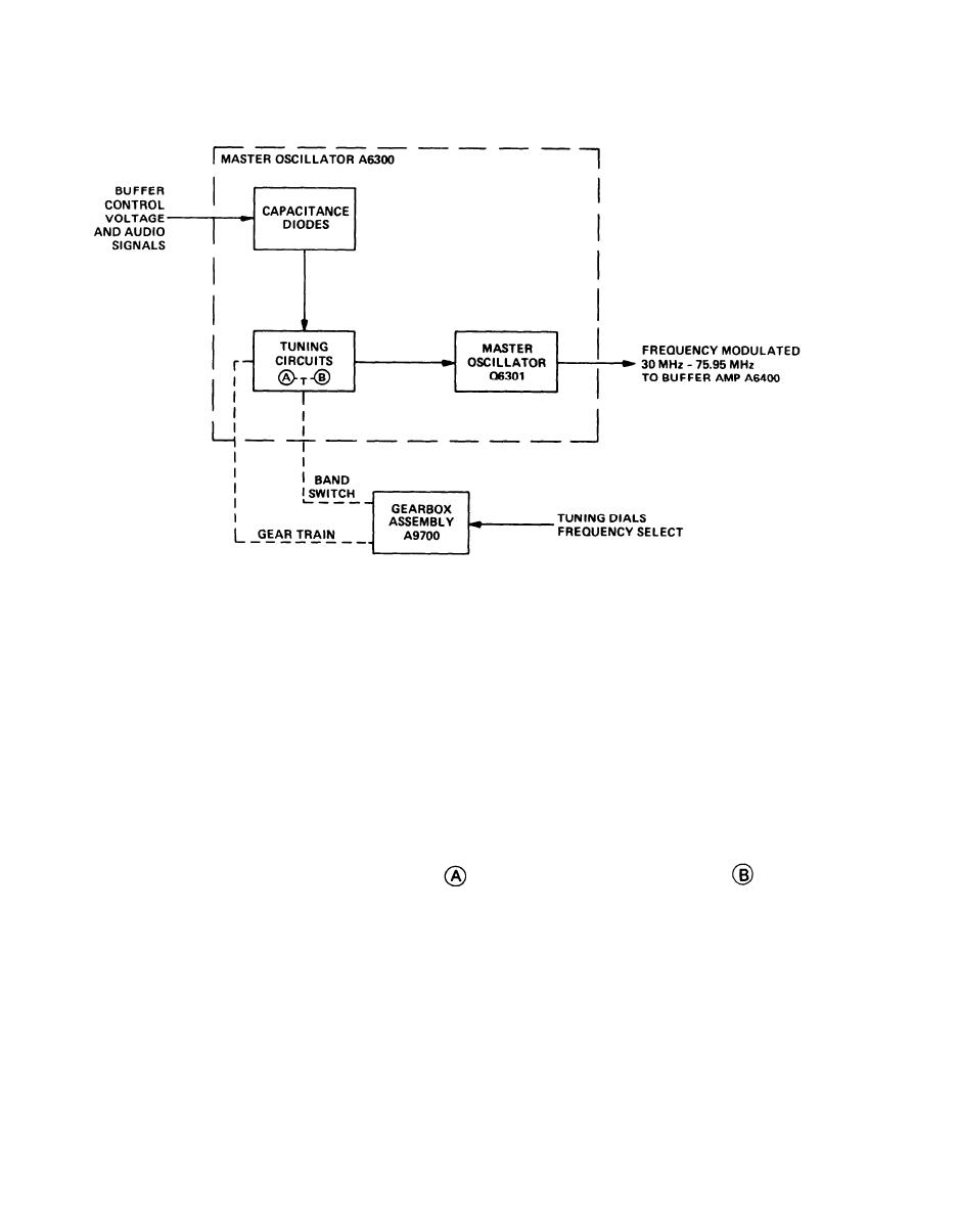
1-40. MASTER OSCILLATOR MODULE A6300.
EL1AT113
The capacitance diodes in the A6300 module accept four signals.
1. 100 Hz sawtooth voltage from hunt generator A8400
2. dc correction voltage from the phase discriminator A8200
3. Voice signals riding on the dc correction voltage
4. 150 Hz tone signal generated in the squelch amplifier A5200
BUFFER CONTROL VOLTAGE
The buffer control voltage consists of 100 Hz sawtooth voltage and dc correction voltage. This
voltage, applied to the capacitance diodes, corrects the frequency of the master oscillator.
TUNING CIRCUITS
The tuning circuits are separated into two bands, an
band, 30 MHz 52.95 MHz, and a
band, 53 MHz 75.95 MHz. The band switch in gearbox assembly A9700 mechanically selects either
band, depending on the operator selected frequency. Resonant circuits comprised of inductors and
capacitors allow the master oscillator to generate the selected frequency. When the operator rotates
the tuning dials for a different channel, the gear train in A9700 mechanically alters the inductance of
resonant circuits causing the master oscillator to change its frequency.
1-40
|
|
Privacy Statement - Press Release - Copyright Information. - Contact Us |
