 |
|||
|
|
|||
|
Page Title:
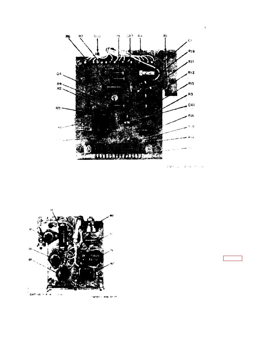
Figure 3-13. AM-2060(*)/GRC, plug-in assembly front view, parts location. |
|
||
| ||||||||||
|
|  TM 115820-498-35
Figure 3-13. AM-2060(*)/GRC, plug-in assembly front view, parts location.
(2) Rotate the switch shaft so that the knob
will be in the proper position when it is replaced
on the shaft.
(3) Replace and tighten the nut; hold the
switch in the proper position until the nut is
tightened.
(4) Replace the knob on the switch shaft,
and secure it i n place with the retaining screw.
316. Rewiring POWER INPUT Connector J3
AM-2060(*)/GRC'S on Orders No. 15108-PP-62
and 5175-PP-64 were wired incorrectly at
POWER INPUT connector J3 (note 10, fig. 49).
Tests to determine the faulty equipment are
given in a below ; rewiring instructions are given
in b below. If the equipment is wired incorrectly
a closed circuit to the dc vehicular dc power ex
i s t s even when the AM2060(*)/GRC PWR
switch is set to OFF.
a. Tests. When the AM2060(*)/GRC PWR
switch is set to OFF, the associated receiver-
transmitter should not be able to be turned on.
Figure 3-14. AM-2060(*)/GRC, plug-in assembly,
However, when the AM-2060(*)/GRC is wired
rear view, parts location.
3-16
|
|
Privacy Statement - Press Release - Copyright Information. - Contact Us |
