 |
|||
|
|
|||
|
|
|||
| ||||||||||
|
|  TM 11-5820-401-34-3/0967-LP-432-3060
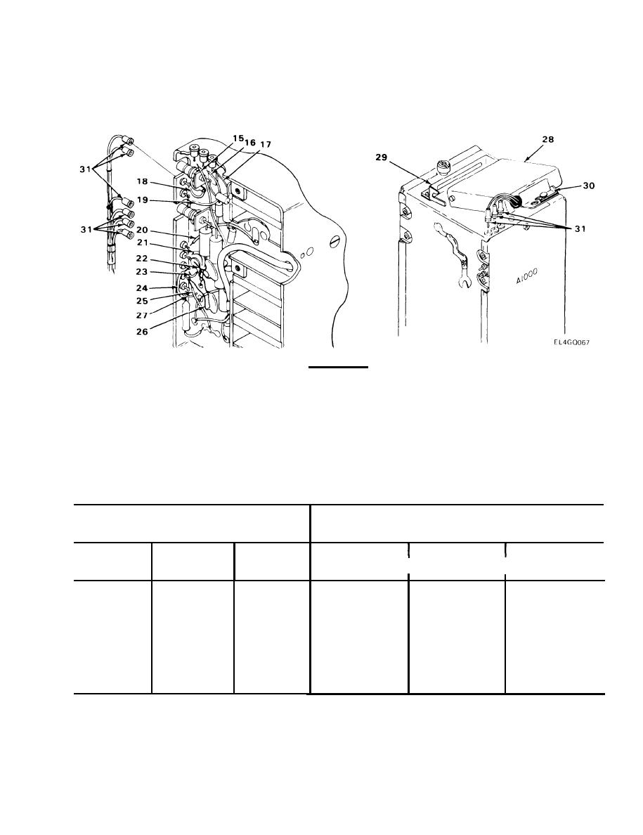
6-5. A1000 ASSEMBLY MAIN CIRCUIT BOARD VR1001 REPLACEMENT. (CONT)
(13) and blue wire (14) to Circuit Board VR1001.
CAUTION
Extreme care must be taken when performing next step to prevent damage to Circuit
Board VR1001 and color-coded wire plugs.
NOTE
If color coding on unit varies from one shown, note corrected color coding before
disassembly.
TOP OF A1000 ASSEMBLY
SEDE OF A1000 ASSEMBLY
I
I
PLUG COLOR
WIRE COLOR
INDEX NO.
PLUG COLOR
WIRE COLOR
INDEX NO.
Brown
Brown
15
Black
Black
18
Purple
Purple
16
White
White
19
Black
Black
17
Yellow
Yellow/White
20
Orange
Orange
21/22
Violet
Violet/White
23/24
Red
Violet
25/26
Brown
Red/White
27
I
I
8. Position A1600 assembly (28) in bracket (29) and push into place.
9. Fasten retaining clip (30) by moving retaining clip to left.
10.
Connect nine color-coded wire plugs (31).
6-13
|
|
Privacy Statement - Press Release - Copyright Information. - Contact Us |
