 |
|||
|
|
|||
|
|
|||
| ||||||||||
|
|  TM 11-5820-401-34-3/0967-LP-432-3060
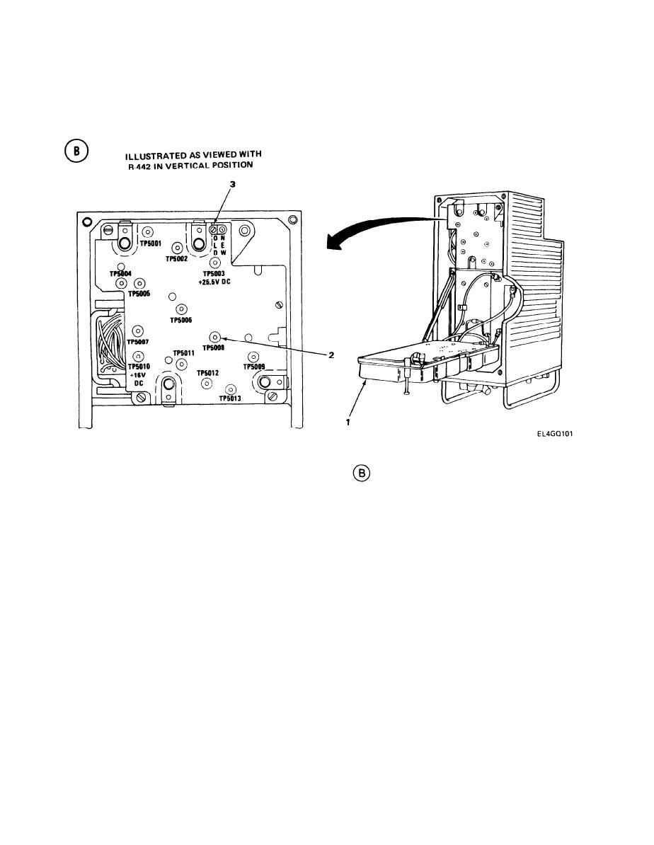
A5200 SQUELCH AMPLIFIER ALINEMENT, OLD SQUELCH LEVEL. (CONT)
5-27.
ALINEMENT PROCEDURE
1. Disconnect rf cable from R-442/VRC ANTENNA port.
2. Lift R-442/VRC A3000 tray (1). (See test setup diagram
.)
3. Set ME-30(*)/U to 10-volt scale.
4. Connect ME-30(*)/U positive lead to TP5008 (2), and negative lead to ground.
5. Set R-442/VRC MC-TUNE-KC control to any frequency that results in at least a 4-vac
reading on ME-30(*)/U. Record ME-30(*)/U reading.
6. Reconnect rf cable to R-442/VRC ANTENNA port.
7. Set AN/URM-103 BAND switch to range that includes R-442/VRC frequency setting.
8. Set AN/URM-103 RF TUNING control to same frequency selected in step 5.
NOTE
correct frequency. The rf level must be increased temporarily to enable the frequency
counter to display. Adjust the AN/URM-103 RF TUNING control as necessary, reset to
20-v rf level; then disconnect the T-connector from the counter.
5-126
|
|
Privacy Statement - Press Release - Copyright Information. - Contact Us |
