 |
|||
|
|
|||
|
Page Title:
LOCAL OSCILLATOR A1500 ALTERNATE ALINEMENT PROCEDURE. |
|
||
| ||||||||||
|
|  TM 11-5820-401-34-3/0967-LP-432-3060
LOCAL OSCILLATOR A1500 ALINEMENT. (CONT)
5-16.
10. Adjust L1501 (4) for clear audio tone and zero-volt reading on ME-26(*)/U. (See test setup
diagram
11. Set R-442/VRC to 42.00 MHz and AN/URM-103 to 42 MHz.
12. Repeat steps 2 through 10 to make sure that local oscillator tracks with no more than 0.5-vdc
error signal required in any of the three test frequencies.
NOTE
If the ME-26(*)/U indicates more than + 0.5 vdc or less than -0.5 vdc in any frequency,
and repetition of steps 2 through 10 does not correct the problem, replace the A1500
assembly.
5-17.
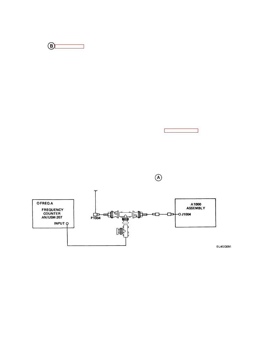
LOCAL OSCILLATOR A1500 ALTERNATE ALINEMENT PROCEDURE.
PURPOSE. This procedure permits alinement of the local oscillator without the use of a signal
presence of an audible audio tone is not important. Thus, alinement does not depend on the per-
formance of the A4000 or A5000 sections of the receiver. The CRS Test (paragraph 5-15) must be
done prior to performing this alinement.
TEST EQUIPMENT AND MATERIALS
Multimeter ME-26(*)/U
Frequency Counter AN/USM-207
One extra SMC rf cable
Amphenol Adapters (two) M-39012/16
T-Connectors (two) UG-274/U
TEST SETUP. Connect equipment as shown in test setup diagram
.
5-96
|
|
Privacy Statement - Press Release - Copyright Information. - Contact Us |
