 |
|||
|
|
|||
|
Page Title:
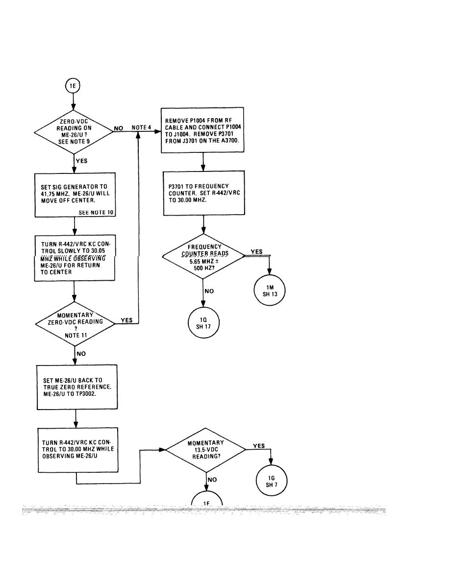
CHART 5-1. No Audio Troubleshooting (Sheet 6 of 18) |
|
||
| ||||||||||
|
|  TM 11-5820-401-34-3/0967-LP-432-3060
5-13. TROUBLESHOOTING FLOW CHARTS. (CONT)
CHART 5-1
No Audio Troubleshooting
(Sheet 6 of 18)
NOTES
9. With R442/VRC set at 30.00 MHz and 41.5
MHz injected into F L3002, there should be no
error signal from the CRS. The meter will
remain centered.
10. This setting should force the CRS to output
a dc error voltage. The voltmeter will indi-
cate this voltage.
11. If the Time Delay Relay K3001 fails to
momentarily short the dc error signal, the
CRS can shift the local oscillator 1 MHz.
12. Since previous steps confirmed presence of
audio tone when CRS was isolated from other
stages, the local oscillator can be considered
alined. Therefore, CRS must be generating
incorrect error signal, driving local oscillator
off frequency.
5-42
|
|
Privacy Statement - Press Release - Copyright Information. - Contact Us |
