 |
|||
|
|
|||
|
|
|||
| ||||||||||
|
|  TM 11-5820-401-34-3/0967-LP-432-3060
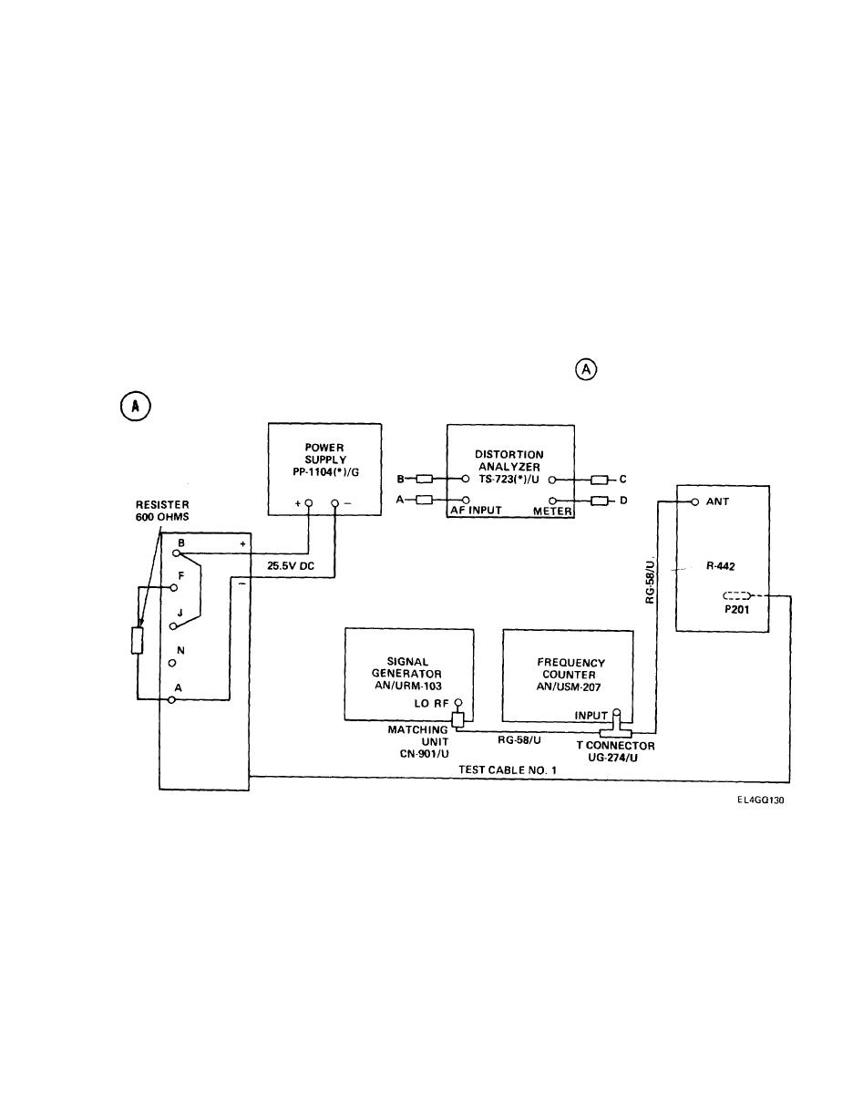
5-7. RECEIVER AUDIO DISTORTION TEST. (CONT)
TEST EQUIPMENT AND MATERIALS
Matching Unit CN-901/U
Power Supply PP-1104(*)/G
Resistor, 600-ohm 5%, 2-watt
Distortion Analyzer TS"723(*)/U
Rf Cables (two) RG.58/U
Frequency Counter AN/USM-207
Test Cable No. 1
Signal Generator AN/URM-103
Adapter (T-Connector) UG-274 B/U
NOTE
The 600-ohm resistor provides an impedance matching load for the audio transformer.
The resistor is used in place of Loudspeaker LS-454/U, which would issue a loud,
distracting tone when the R-442/VRC VOLUME control is adjusted during the test. If no
600-ohm resistor is available, however, the loudspeaker must be connected.
.
TEST SETUP. Connect test equipment as shown in test setup diagram
Turn on test equipment. Allow at least 15 to 30 minutes for warmup.
5-19
|
|
Privacy Statement - Press Release - Copyright Information. - Contact Us |
