 |
|||
|
|
|||
|
|
|||
| ||||||||||
|
|  TM 11-5820-401-34.3/0987-LP-432-3060
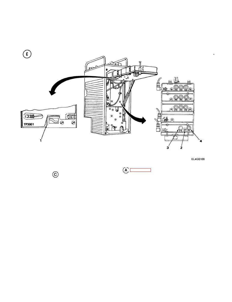
4-16. LOCAL OSCILLATOR A1500 ALINEMENT. (CONT)
ALINEMENT PROCEDURE
Adjust AN/GRM-114A VERT control to zero scope trace.
1.
2.
Connect MK-1978/VRC test probe (test setup diagram
, page 4-114) to TP3001 ((1)test
setup diagram
), and alligator clip to ground.
NOTE
Probe must be on x10 setting for correct scope reading.
Due to a 3.5-kHz local oscillator tolerance with the CRS operating, it may not be
possible to achieve a zero-vdc scope trace in the following steps. The dc voltage should
not exceed & 0.5 volts.
3.
Adjust C1501 (2) for zero-vdc scope reading.
4.
Set R-442/VRC MC-TUNE-KC control to 30.00 MHz.
5.
Set AN/GRM-l14A RF FREQUENCY MHz thumbwheels to 030000 0.
6.
Adjust L1502 (3) for zero-vdc scope reading.
7.
Set R-442/VRC MC-TUNE-KC control to 52.00 MHz.
8.
Set AN/GRM-l 14A RF FREQUENCY MHz thumbwheels to 052000 0.
9.
Adjust L1501 (4) for zero-vdc scope reading.
10.
Repeat steps 3 through 9 until scope reads as close to zero vdc as possible for all
three frequencies, with clear audio.
4-116
|
|
Privacy Statement - Press Release - Copyright Information. - Contact Us |
