 |
|||
|
|
|||
|
|
|||
| ||||||||||
|
|  TM 11-5820-401-34-3/0967-LP-432-3060
3-22. SILICON VERSION AUDIO AND SQUELCH PREAMPLIFIER A4300A ALINEMENT. (CONT)
CONTROL AND SWITCH SETTINGS (CONT)
EQUIPMENT
CONTROL OR SWITCH
POSITION/SETTING
MK-1978/VRC
POWER
ON
AUX RCVR
NORMAL
AUDIO
MUTED
SQUELCH
ON
KEY
RCVE
ALINEMENT PROCEDURE
NOTE
64 MHz. The rf level must be increased temporarily to enable the frequency counter to
display. Adjust the AN/URM-103 RF TUNING control as necessary, reset to 10-v rf
level; then disconnect the T-connector from the counter.
1.
Turn AN/URM-103 DEVIATION control clockwise until DEVIATION KHZ meter reads 8 kHz.
2.
Set ME-30(*)/U to 1-volt scale.
3.
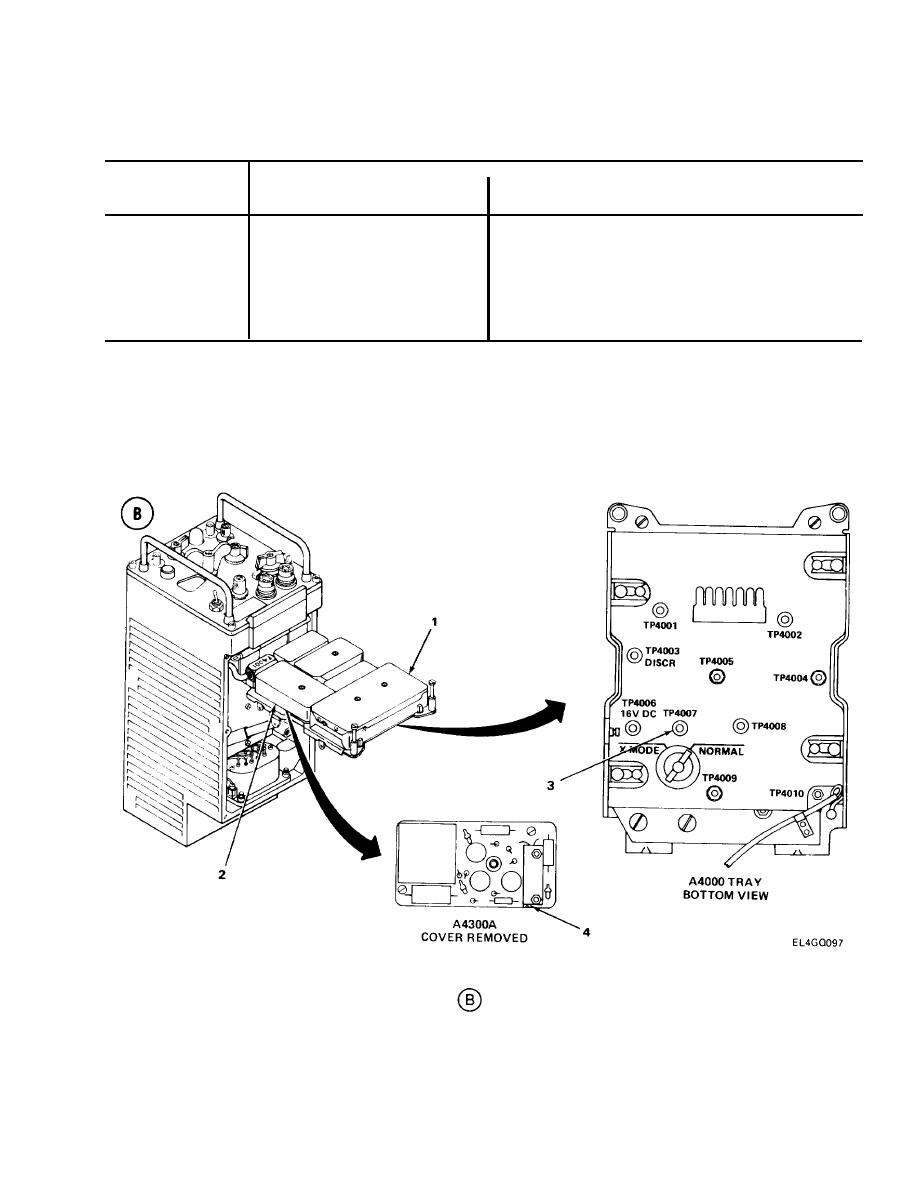
Lift A4000 tray (1). (See test setup diagram
.)
4.
Remove A4300A cover (2).
Connect ME-30(*)/U positive lead to TP4007 (3) and negative lead to ground.
5.
Adjust R4304(4) for 0.8-vac reading on ME-30(*)/U.
6.
3-111
|
|
Privacy Statement - Press Release - Copyright Information. - Contact Us |
