 |
|||
|
|
|||
|
Page Title:
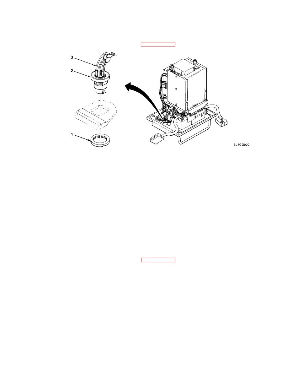
AUDIO CONNECTOR J103 AND J104 REPLACEMENT |
|
||
| ||||||||||
|
|  TM 11-5820-401-34-3/0967-LP-432-3060
2-17.
AUDIO CONNECTOR J103 AND J104 REPLACEMENT
MATERIALS/PARTS: Electrical Connector Assembly, P/N SMC415681
PRELIMINARY PROCEDURE: Remove front panel (See paragraph 2-8.)
REMOVAL
NOTE
The steps given are typical of both connectors. The only difference is that Connector
J103 has six wires and Connector J104 has five wires.
1. Using spanner wrench, remove locknut (1).
2. Carefully push connector (2) out of panel.
3. Using soldering iron, carefully remove and resolder wires (3) from defective connector to re-
placement connector one at a time. (See note for number of wires on each connector.)
INSTALLATION
1. Carefully push connector (2) back into panel.
2. Install locknut (1) on connector (2).
3. Using spanner wrench, tighten locknut (1).
FOLLOW-ON MAINTENANCE: Install front panel. (See paragraph 2-8.)
2-28
|
|
Privacy Statement - Press Release - Copyright Information. - Contact Us |
