 |
|||
|
|
|||
|
|
|||
| ||||||||||
|
|  TM 11-5820-401-34-3/0967-LP-432-3060
2-8.
FRONT PANEL REPLACEMENT. (CONT)
14.
Position P4001 (6) on pins and push into place.
15.
Using screwdriver, tighten two captive screws (7).
16.
Release brace (8) and lower A4000 assembly (9) into position.
17.
Using screwdriver, tighten two captive screws (10).
FOLLOW-ON MAINTENANCE: install top and bottom covers. (See paragraph 2-7.)
2-9.
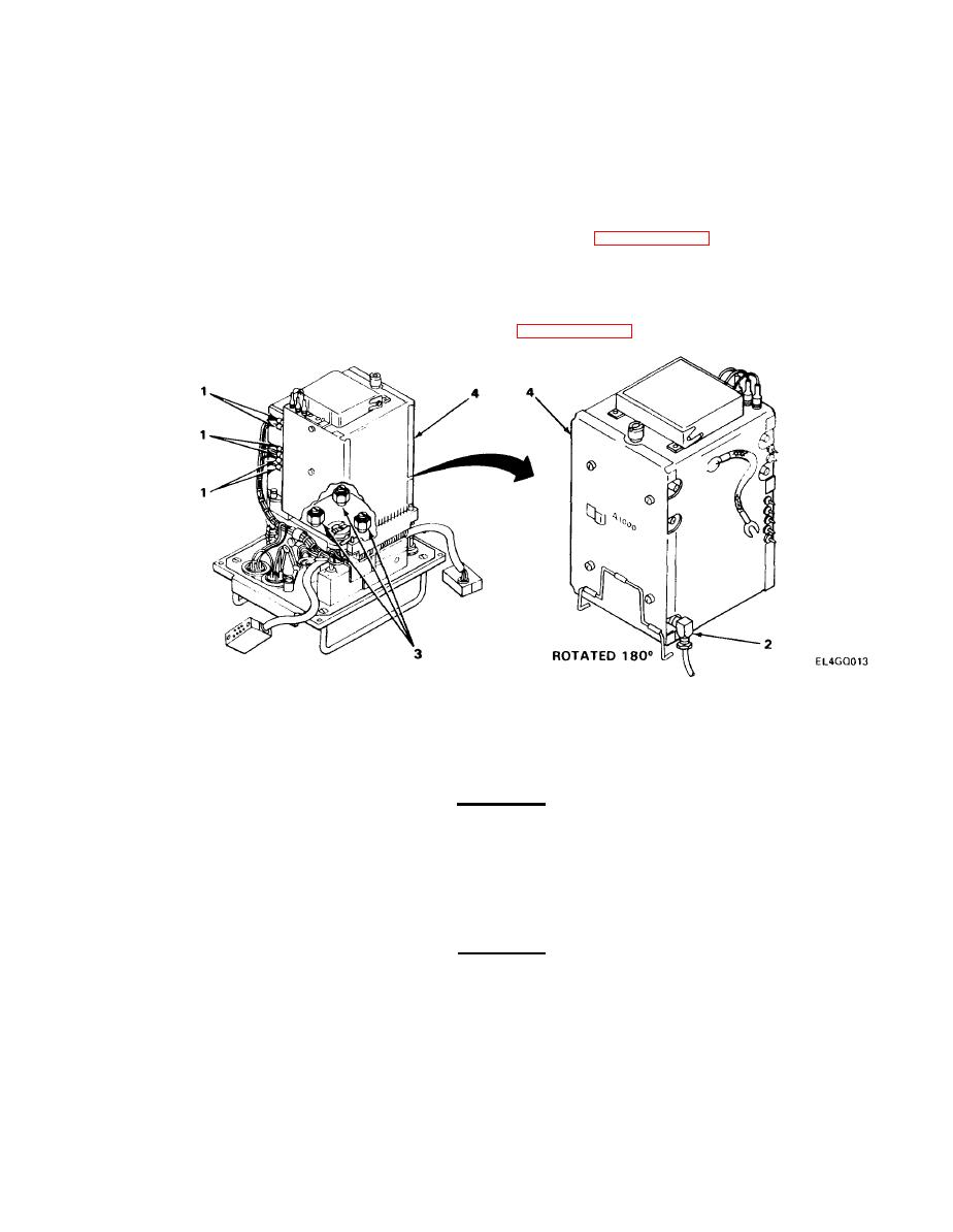
A1000 ASSEMBLY REPLACEMENT.
MATERIALS/PARTS: Radio Frequency Tuning Unit, A1OOO
PRELIMINARY PROCEDURE: Remove front panel. (See paragraph 2-8.)
REMOVAL
1. Disconnect six color-coded wire plugs (1).
2. Disconnect brown wire (W102) (2) from J1001.
CAUTION
Care must be taken when performing next step to prevent damage to vhf tuner linkage
arm.
3. Using wrench, loosen three captive nuts (3).
4. Remove A1000 assembly (4).
CAUTION
Note relative positions of gear train couplers on A1000 assembly and rent panel. Do not
turn any of them.
2-15
|
|
Privacy Statement - Press Release - Copyright Information. - Contact Us |
