 |
|||
|
|
|||
|
Page Title:
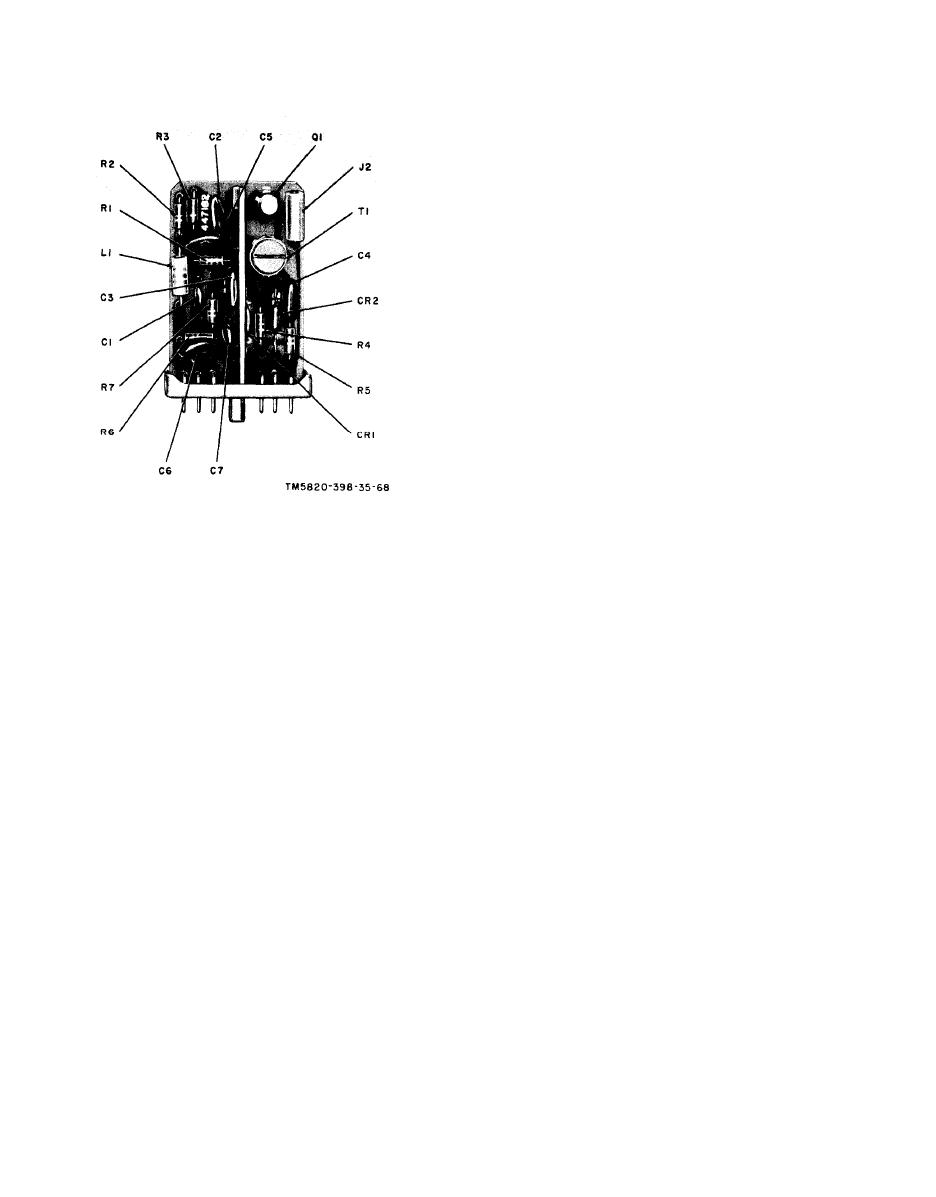
Figure 69. Module A17, parts location |
|
||
| ||||||||||
|
|  (2) Adjust the AN/URM-25F signal
level to 1.5 millivolts, as indicated
by the 411A.
(3) Disconnect the 411A from the AN/
URM-25F and connect it between
A18J2 and chassis ground.
(4) Adjust the AN/URM-25 frequency
to 5.3000 mc as indicated by the
AN/USM-26. Normal 411A indica-
tion at A18J2 should be 0.07 volt
rms.
(5) Adjust the AN/URM-25F frequency
to 5.9000 mc as indicated by the
AN/USM-26. Normal 411A indica-
tion at A18J2 should be 0.07 volt
rms.
(6) If the indications obtained in the
procedures given in (4) and (5)
above are not normal, proceed to
d below. (Do not disturb test equip-
ment settings.)
(7) If the indications obtained in (4) and
(5) above are normal, the A18 test-
ing is completed.
Figure 69. Module A17, parts location
d. Alignment Procedure.
(1) Connect the 411A across the AN/
URM-25F output.
(2) Adjust the AN/URM-25F frequency
b. Gain Test.
to 5.6000 mc as indicated by the
(1) Connect the AN/URM-25F be-
AN/USM-26 and the level to 1.5
tween pin F of A18J1 and ground.
millivolts, as indicated by the
Connect the 411A and the AN/
411A.
U R M - 2 6 across the AN/URM-
(3) Disconnect the 411A from the AN/
25F output.
URM-25 F and connect it between
(2) Adjust the AN/URM-25F frequency
A18J2 and chassis ground.
to 5.6000 mc as indicated by the
(4) Adjust L1, T1, L2, and T2 for peak
AN/USM-26 and the level to 4 mil-
indication on the 411A.
livolts, as indicated by the 411A,
(5) Repeat the procedure given inb and
(3) Disconnect the 411A from the AN/
c above.
URM-25F and connect it between
e. Faulty Parts Isolation.
A18J2 and chassis ground.
(1) Set the AN/URM-25F output fre-
(4) A normal output signal voltage at
quency to 5.600 mc as indicated
A18J2 is 0.1 volt rms, as indicated
by the AN/USM-26 and adjust
by the 411A.
the voltage level between pin F
(5) If a proper indication is not ob-
of A18J1 and chassis ground to
tained, proceed to d below. (Do not
2 millivolts as indicated by the
disturb the test equipment set-
411A.
tings.)
(2) Measure the voltages at the points
(6) If the proper indication is obtained,
listed in the charts given in (a) and
proceed to c below. (Do not disturb
(b) below. Compare these with the
the test equipment settings.)
normal signal and dc voltages
c. Bandwidth Test.
listed.
(1) Connect the 411A across the AN/
URM-25F output.
Note: Measure all voltages to ground.
134
|
|
Privacy Statement - Press Release - Copyright Information. - Contact Us |
