 |
|||
|
|
|||
|
Page Title:
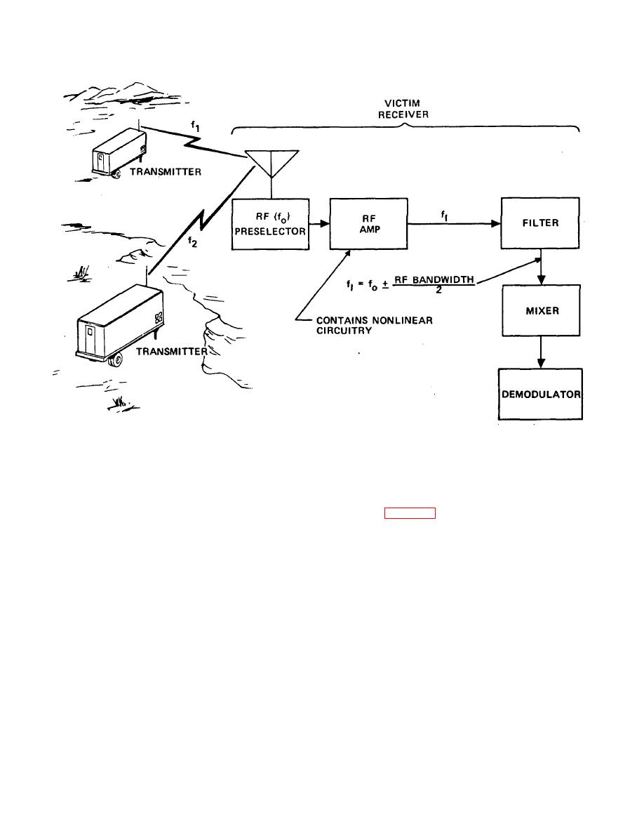
Figure 2-4. Intermodulation products occurring at a receiver. |
|
||
| ||||||||||
|
|  TM 11-490-5
Figure 2-4. Intermodulation products occurring at a receiver.
production and transmission of 7th order intermodulation
3. Intermodulation products may also occur in a
products which could interfere with a 50-MHz link is
link transmitter as a result of the mixing of signals from
shown in figure 2-5. Interfering signals entering the link
two interfering transmitters in the final stage of the link
transmitter antenna are mixed in the final stage and
transmitter. Intermodulation products are generated in
retransmitted as 7th order intermodulation product
the final stage according to the' same equation
signals according to the following relationship:
presented for receiver intermodulation products. The
transmitted signal consists not only of the desired signal,
fI = 4fa - 3fb
properly modulated, but the intermodulation products
= 4(51.2) - 3(51.6) MHz
also at the desired signal frequency (or, at least, within
= 204.8 - 154.8 MHz
the RF bandwidth of the link receiver).
The
= 50.0 MHz
intermodulation product signals will contain vestiges of
the interfering signal modulations which will be heard as
Therefore, fI = f0 = 50.0 MHz.
noise at the link receiver. An example of the
2-7
|
|
Privacy Statement - Press Release - Copyright Information. - Contact Us |
