 |
|||
|
|
|||
|
|
|||
| ||||||||||
|
|  TB 9-2320-280-35-7
NOTE
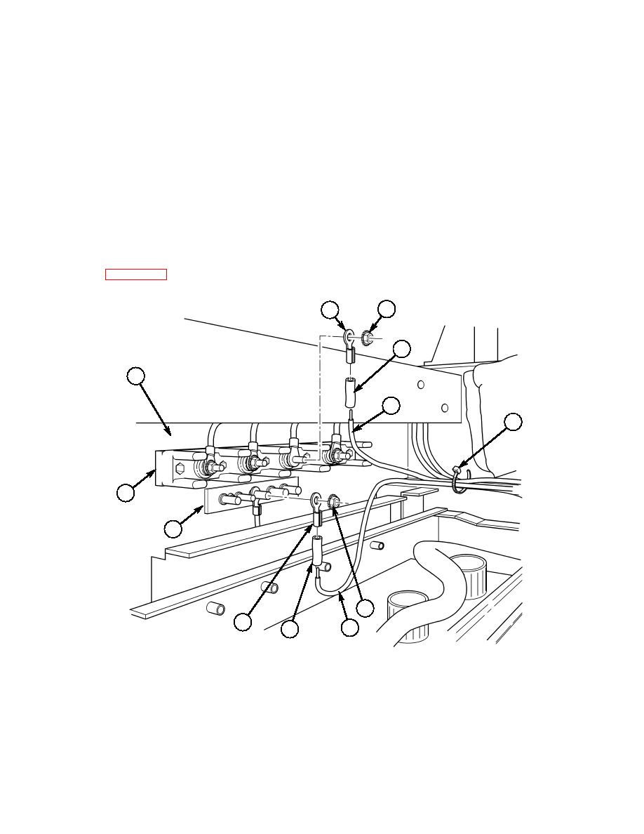
PLGR power cable positive lead insulation is ribbed.
19-23. Attach shrink tubing (37) and terminal lugs (35) and (41) to PLGR power cable negative lead (40)
and PLGR power cable positive lead (38). (Refer to TM9-2320-280-20 for terminal connector repair.)
19-24. Attach PLGR power cable positive lead (38) to 24-volt terminal board (43), located on cab enclosure
panel (34), with existing nut (36).
19-25. Attach PLGR power cable negative lead (40) to ground strap (42), located on cab enclosure
panel (34), with existing nut (36).
19-26. Coil excess positive and negative power leads (38) and (40), place beneath ground strap (42), and
secure with tiedown strap (39).
NOTE
Ensure all excess antenna cable is inside cab of vehicle.
19-27. Coil excess antenna cable and store under integrated rack using tiedown strap as necessary. (Refer
19-28. Install right-side tunnel insulation. (Refer to TM 9-2320-280-20.)
36
35
37
34
38
39
~
43
42
36
41
40
37
35.
TERMINAL LUG 7728780 QTY. 1
37.
SHRINK TUBING MS23053/4-302-0 QTY. A/R
39.
TIEDOWN STRAP MS3367-1-0 QTY. A/R
41.
TERMINAL LUG 7728777 QTY. 1
Figure. 5-51.
5-40
|
|
Privacy Statement - Press Release - Copyright Information. - Contact Us |
