 |
|||
|
|
|||
|
|
|||
| ||||||||||
|
| 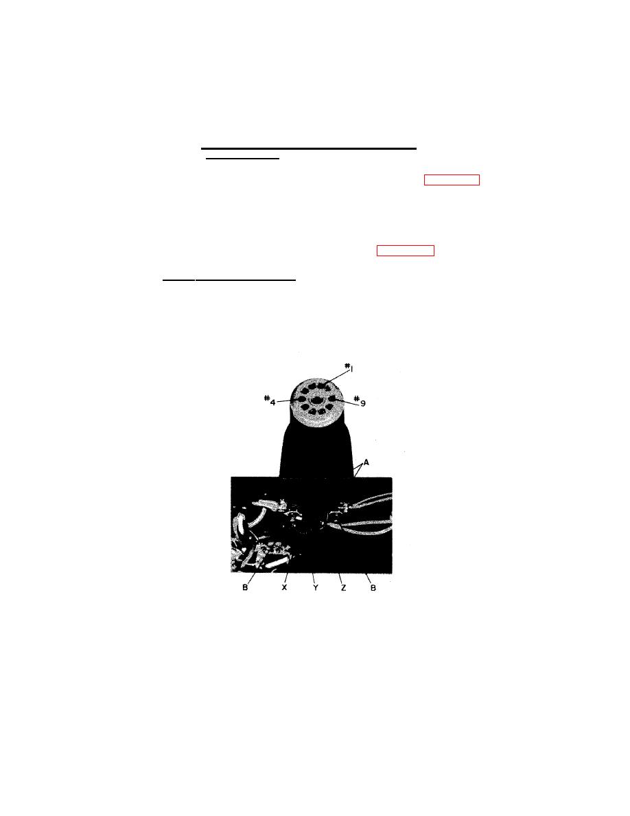 c. Unsolder the three swivel-support assembly leads (X, Y, Z)
and remove the assembly.
NOTE
If desired, the pivot blocks and washers may
now be replaced.
d. Position the new swivel-support assembly so that the strobotron
tube socket and leads (X, Y, Z) can be mounted as shown in Figure 4-4.
e, Insert leads (X, Y, Z) through the slot between screws (B),
and hold the swivel-support assembly in position between the two pivot
blocks. Slide the pivot blocks together and tighten nuts (A). The pivot
action of the swivel-support assembly may need adjustment; if so,
loosen one nut (A), adjust the corresponding pivot block, and tighten
the nut again.
f. Solder leads (X, Y, Z) to terminals (see Figure 4-4).
To replace the scale-mask assembly:
a. Set the range switch to the 4000-25,000 RPM position.
b. Loosen the two setscrews in the scale-mask assembly hub
and remove the assembly from the range-switch shaft.
Strobotac. Lead connection terminals
and mounting of swivel-support assembly.
33
|
|
Privacy Statement - Press Release - Copyright Information. - Contact Us |
