 |
|||
|
|
|||
|
Page Title:
REPLACEMENT OF MECHANICAL PARTS. |
|
||
| ||||||||||
|
| 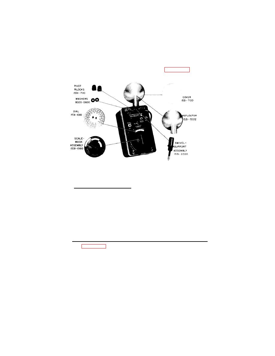 4-7. REPLACEMENT OF MECHANICAL PARTS.
Although the stroboscope is designed for use in manufacturing,
test, and other areas where the working environment is often unsuitable
for precision electronic instruments, certain mechanical parts mounted
on the outside of the instrument case may eventually become contain -
inated or damaged. To replace these parts (see Figure 4-3), refer to
the following instructions.
Type 1531 Strobotac.
4.7.1 REFLECTOR AND COVER.
Remove the old reflector by pulling it away from the swivel-
support assembly. Mount the new reflector sliding it onto the swivel -
support assembly until the spring-loaded detent button snaps into the
groove inside the reflector base.
To replace the reflector cover, remove the old cover by pushing
on the edge at each of the three flanges that clamp over the rim of the
reflector housing. Then, mount the new cover by pulling the edge of
the cover toward the rim of the reflector housing until the three flanges
snap securely in place.
4.7.9 SWIVEL-SUPPORT ASSEMBLY, PIVOT BLOCKS, AND WASHERS.
See Figure 4-4. To replace the swivel-support assembly:
a. Remove the reflector, the strobotron lamp, and then remove
the instrument from its case.
b. Loosen (do not remove) two nuts (A) and slide the two pivot
blocks apart. (The heads of the two screws (B) clamp the pivot blocks
in position when nuts (A) are tightened.)
32
|
|
Privacy Statement - Press Release - Copyright Information. - Contact Us |
