 |
|||
|
|
|||
|
Page Title:
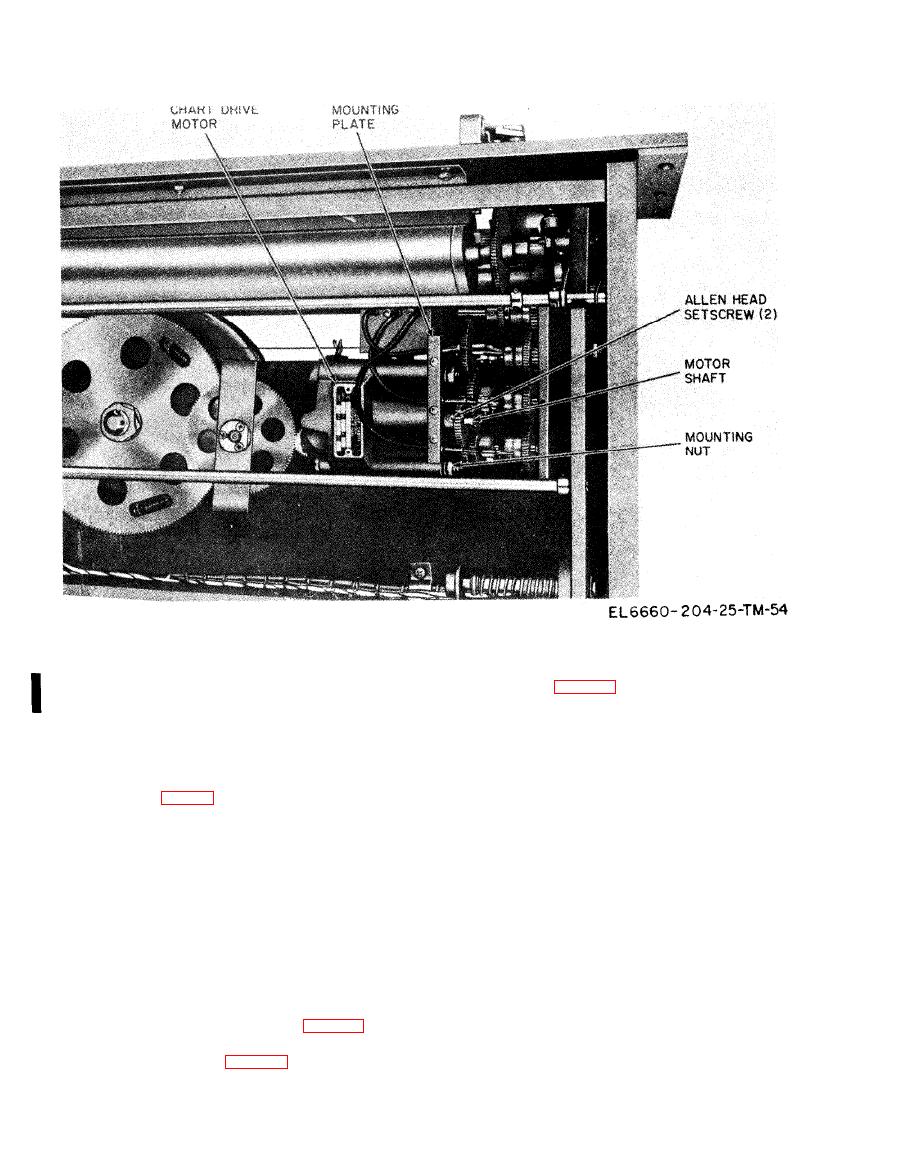
Figure 4-17. Balancing Motor Mounting. |
|
||
| ||||||||||
|
|  TM 11-6660-204-25
tor pinion gear (fig. 4-18) to the motor shaft and
Motor and Gear Assembly
remove the pinion gear from the motor shaft.
( 7 ) Remove the balancing motor from the
a. Removal.
frequency-time recorder chassis.
(1) Remove the frequency-time recorder chassis
(8) Replace any gear mechanism components if
from the cabinet.
required, in the exact same position as the compo-
(2) Insert a piece of wood between the intermedi-
nents removed.
ate gear assembly (fig. 4-18) and the split gear as-
b. Replacement. Install a new balancing motor as
sembly. Make sure that the piece of wood fits snugly
follows. Make sure that the gear assemblies mesh
between the gear assemblies.
properly and are in the same relative position they
(3) Secure the gear assembly with masking tape
were in before the motor was replaced.
to prevent movement.
(1) Install the balancing motor in the frequency-
CAUTION
time recorder chassis.
The balancing motor gear assemblies
(2) Install the pinion gear on the motor shaft and
must remain in a fixed position during the
install the retaining nut.
replacement of the balancing motor. Be
(3) Install the studs and secure the motor to the
sure that the gears will not turn before
chassis.
proceeding with the removal of the motor.
(4) Connect the tagged motor leads.
(4) Tag and remove the balancing motor con-
(5) Remove the masking tape and thoroughly
necting leads from the terminal board (fig. 4-16).
remove any residue.
(5) Remove the balancing motor studs from the
(6) Remove the wood from the gear assemblies.
top of the balancing motor (fig. 4-16).
(7) Reinstall the frequency-time recorder in the
(6) Remove the nut that holds the balancing mo-
cabinet.
Change 3
|
|
Privacy Statement - Press Release - Copyright Information. - Contact Us |
