 |
|||
|
|
|||
|
Page Title:
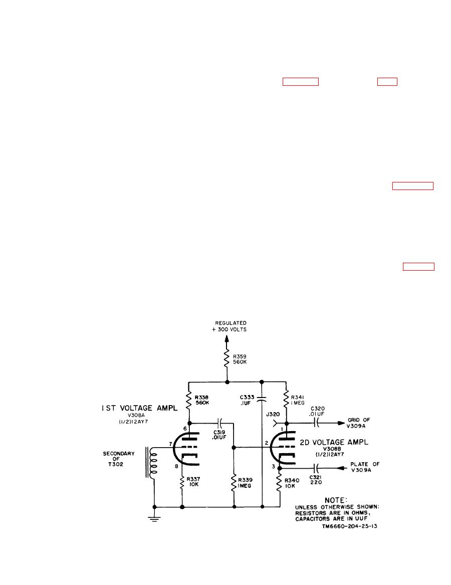
Voltage Amplifiers |
|
||
| ||||||||||
|
|  TM
11-6660-204-25
produces an effective braking action, and prevents
greater than the slide-wire voltage. This causes an
overshooting the balance point.
ac error voltage to appear at the detector, which
acts to drive the slide-wire in a direction to bal-
ance out this voltage. As the slide-wire voltage
214. Voltage Amplifiers
rises toward the balanced condition, a charging
current is produced in capacitor C315 (developed
Five stages of voltage amplification are used to
by the movement of the slide-wire arm, dependent
increase the ac error voltage from the detector to
on its speed) which is in a direction opposite to
excite the power amplifiers, and drive the balanc-
that of the current produced by the original dc
ing motor. The first four stages are very stable,
e r r o r voltage. As the dc slide-wire voltage
because all operating voltages, including the fila-
changes to equal the dc applied voltage at balance,
ments, are obtained from regulated power sup-
the original current developed in capacitor C315
plies. The gain of the remainder of the servo sys-
and the error voltage developed in the detector is
tem varies inversely with the line voltage. Line-
reduced to zero. The opposing capacitor-charging
compensating feedback is incorporated in the am-
current is developed as long as the slide-wire is
plifier to compensate for line voltage variations to
moving; when the balance point is approached the
stabilize the overall gain of the servosystem. Fig-
opposing capacitor current will exceed the current
ures 212, 213 and 2-14 show all cathode resis-
that produces the error voltage. As this opposing
tors are unbypassed. This produces a degenerative
current is developed in the detector, an effective ac
circuit action and is done to further stabilize the
balancing voltage is developed in opposition to the
gain of the amplifier.
original ac error voltage; thus a reverse torque is
applied to the balancing motor for braking action.
a. When an unbalance occurs in the detector, ac
error voltage is developed in the secondary wind-
e. During any condition of unbalance, two op-
posing currents flow through the detector: one is
ing of transformer T302 and is applied to the grid
determined by the amount and direction of unbal-
of tube V308A, one-half of a twin-triode (fig. 2
ance, and the other by the speed and direction of
12). This signal is amplified and appears across
balancing response. Two opposing voltages are de-
plate-load resistor R338. Self-bias is provided by
veloped in the detector circuit: one tends to drive
cathode resistor R337, which is unbypassed to ob-
the slide-wire arm in one direction, and the other
tain negative feedback.
tends to drive it in the opposite direction. This
|
|
Privacy Statement - Press Release - Copyright Information. - Contact Us |
