 |
|||
|
|
|||
|
|
|||
| ||||||||||
|
|  TM
11-6660-204-25
b. Tube V305A has its grid connected to the
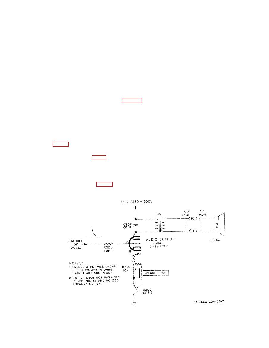
b. The grid of tube V304B is directly connected
through current-limiting resistor R320 to the
+300-volt supply through resistor R328 so that it
is normally in a conducting condition when no sig-
cathode of tube V304A and is supplied with a
nal is applied. Biasing is accomplished by the flow
fixed negative bias of 12.6 volts. When the posi-
of grid current through resistor R328, and develops
tive streched pulse appears at the cathode of tube
V304A, it is applied to the grid of tube V304B
a bias which is sufficient to produce a voltage drop
across R328 almost equal to the voltage supply.
through grid-current limiting resistor R320. Be-
Normally, with no signal applied, the grid rests at
cause of the large signal amplitude swing, the
a potential of +4 or +5 volts. Because tube V305
tube draws a slight amount of grid current on the
is a high-gain triode, it requires only a small volt-
signal peaks through resistor R320 effectively
age for cutoff (approximately --5 volts at 300
clipping the spiked portion of the signal and pro-
plate volts ). With a positive voltage on the grid,
ducing a pleasing sound in the speaker. The signal
the tube conducts to produce a plate current flow
is amplified and fed through audio output trans-
former T301 to the speaker mounted on the con-
of approximately 4 milliamperes (ma), and a
cathode potential of approximately 4 volts. In op-
trol panel. A simplified diagram is shown in figure
2-6. The cathode of tube V304B is returned to
eration the grid voltage is slightly higher than the
developed cathode voltage, so the tube normally
circuit ground through unbypassed potentiometer
R214. This potentiometer has no shunt capacitor
operates with a small positive bias. The grid of
tube V305B is directly connected to the plate of
and effectively controls the amount of negative
feedback, tube gain, and speaker volume,
tube V305A through resistor R324 and is biased
beyond cutoff by a voltage divider arrangement
2 - 1 0 . Univibrator
which consists of resistors R324, and R325, and
R326, between that + 50-volt plate of tube V305A
and --175 volts, This bias is adjustable through
a. The univibrator uses both sections of a mini-
variable resistor R326. Resistor R322 is the cath-
ature twin-triode tube, V305 (fig. 2-7). The univi-
ode resistor for tube V305A, and R329 is the cath-
brator is essentially a one-shot multivibrator trig-
ode resistor for tube V305A. The input trigger
gered by the output of the preceding pulse select-
voltage is applied to the cathode of tube V305A
or circuit. Its purpose is to generate a positive-
and the output signal is taken from the grid of
going rectangular pulse of constant time width to
operate voltage switch V306 (fig. 2-8).
tube V305A and applied to voltage switch tube
|
|
Privacy Statement - Press Release - Copyright Information. - Contact Us |
