 |
|||
|
|
|||
|
|
|||
| ||||||||||
|
|  TM
11-6660-204-25
Section Il. STAGE FUNCTIONING
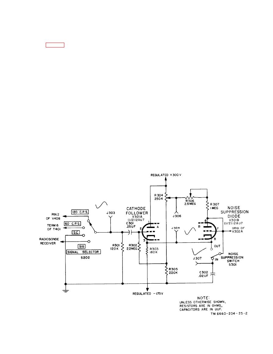
a. The cathode follower circuit receives its
i n p u t signal through. SIGNAL SELECTOR
switch S202, which is mounted on the control
Cathode follower V301A is one-half of a minia-
panel. This switch has four positions and its rotor
ture twin-triode tube which functions as a buffer
contact is connected to) the input (grid) of the
or isolating stage and offers a sufficiently high
c a t h o d e follower. One position, S.C. (short
input impedance to prevent loading of the output
circuit ), is used to ground the input, and effects a
circuit of the radiosonde receiver (which supplied
zero indication on the recorder. Two test-voltage
signals to the recorder). The cathode follower
positions, 60 CPS and 120 CPS, supply either a
presents a low output impedance to the noise-sup-
60- or 120-CPS signal to the input circuit, which
pression circuit and the input signals can be in
makes the recorder indicate a reference level of 30
the form of sine waves, exponential waves, saw-
or 60 chart divisions, respectively, when REF.
tooth waves, or pulses, depending on the type of
ADJUST potentiometer R202 is correctly set. The
equipment with which the recorder is used. For
fourth position, SIG., applies the radiosonde re-
ease of presentation, all wave forms shown on the
ceiver output signal to the cathode follower input.
simplified diagrams in this chapter are taken with
b. The input signal voltage is applied across
SIGNAL SELECTOR switch S202 in the 120 CPS
position. The input test signal in this instance is
resistor R301 and through de blocking capacitor
the 120-cycle ripple voltage taken from the nega-
C301 to the grid of tube V301A. The plate is con-
nected directly to the low impedance 300-volt posi-
tive power supply ahead of the filter; the shape of
the wave is between a sawtooth and sine. The 60
tive supply. Voltage-dividing resistors R304 and
R305 reduce the positive potential to a nominal
cps test voltage is a sine wave taken directly from
140 volts for use as a "bias potential for the grid
the power transformer in the power supply.
simplified schematic diagram.
|
|
Privacy Statement - Press Release - Copyright Information. - Contact Us |
