 |
|||
|
|
|||
|
Page Title:
Test Set, Trouble Localization Chart |
|
||
| ||||||||||
|
|  TM 11-6625-847-12
dicated do not result in correction of the trouble, a
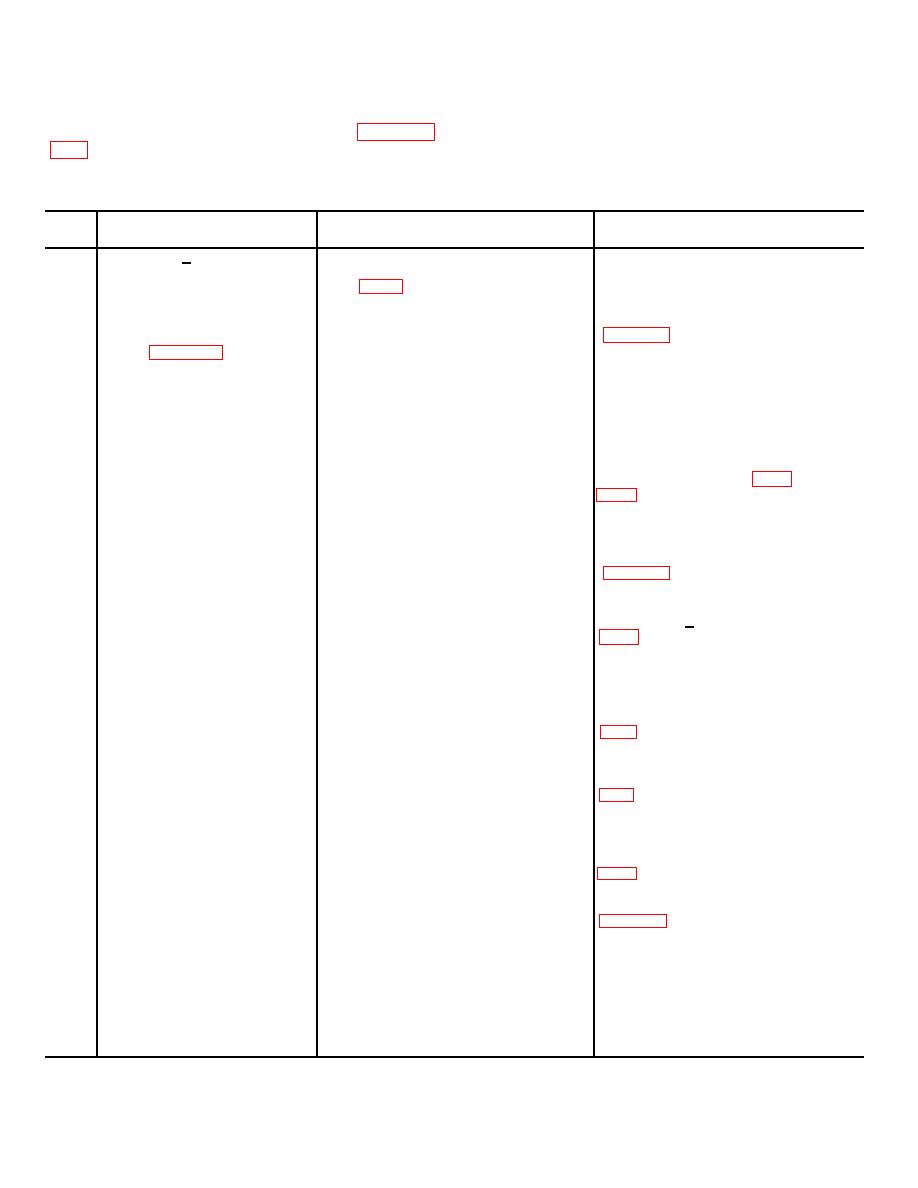
4-14. Test Set, Trouble Localization Chart
higher category of maintenance is required. Paragraph
The chart below specifies the performance required to
be sure that the test set is operational.
be used during the replacement and adjustment
procedures.
Step
Control setting and
Performance standard and
No.
Operation of test equipment
operation of equipment
references
1
Be sure that +27-dc pri-
Set switches and controls on test
mary power is supplied
set to setting listed in para-
to test set POWER con-
graph 3-10.
nector.
Set POWER switch to ON ----------------
POWER indicator illuminates
3
Refer to figure 4-1 for
Rotate SERV SEL switch to
test equipment; energize
OVEN ON. Adjust DC VOLT-
the equipment and allow X
AGE 20 control for +20-volt
30 minutes for warmup.
indication on AN/PSM-6.
Connect AN/PSM-6 dc
test leads to DC VOLT-
AGE test points +20
and (ground).
4
Use AN/USM-207 to
Adjust IF OSCILLATOR 1 1.75
1.750000 mc + 100 cps (para
measuse frequency at IF
MC output level control for an
OSCILLATOR 1 1.75
indication on AN/USM-207
MC OUT connector.
counter.
5
Disconnect AN/USM-207
Rotate IF OSCILLATOR 1 1.75
Output rf level should vary from
from IF OSCILLATOR
MC output level control from
0 to (at least) +300 mv
1 1.75 MC OUT con-
fully counterclockwise to fully
nector and connect ANI
clockwise.
URM-145.
6
Use AN/USM-207 to
Adjust IF OSCILLATOR 2
1.751500 mc + 100 cps (para
measure frequency at
1.7515 MC output level control
IF OSCILLATOR
for an indication on AN/
2 1.7515 MC OUT con-
USM-207.
nector.
7
Disconnect AN/USM -297
Rotate IF OSCILLATOR 2
Output rf level should vary from
from IF OSCILLIATOR
1.7515 MIC output level control
0 to (at least) 300 mv (para
2 1.7515 MC OUT con-
from fully counterclockwise to
nector and connect AN/
fully clockwise.
URM-145.
8
Use AN/USM-207 to
Adjust IF OSCILLATOR 3
1.752500 me 100 cps (para
measure frequency at IF
1.7502 MC output level control
OSCILLATOR 3 1.7525
for an indication on AN/USM-
MC OUT connector.
207.
9
Disconnect AN,/U,SM--207
Rotate IF OSCILI.ATOR 3
Output rf level should vary from
from IF OSCILILATOR
1.7.525 MC output level control
0 to (at least) 300 mv (para
3 1.7525 MC OUT con-
from fully counterclockwise to
nector and connect AN/
fully clockwise.
URM-145.
10
Set AN',TRM-127 to 5%(h
Adjust PULSE GENERATOR
Para 4-15, No. 8.
cps at 5-volt amplitude.
(lower) WIDTH and AMPLI-
Connect output of AN/
TUDE controls for a 1-usec,
URM-127 to PULSE
1-volt positive pulse indication.
GENERATOR INPUT
connector. Connect AN/
USM-140 to PULSE
GENERATOR OUT-
PUTS 3 connector.
4-4
|
|
Privacy Statement - Press Release - Copyright Information. - Contact Us |
