 |
|||
|
|
|||
|
|
|||
| ||||||||||
|
| 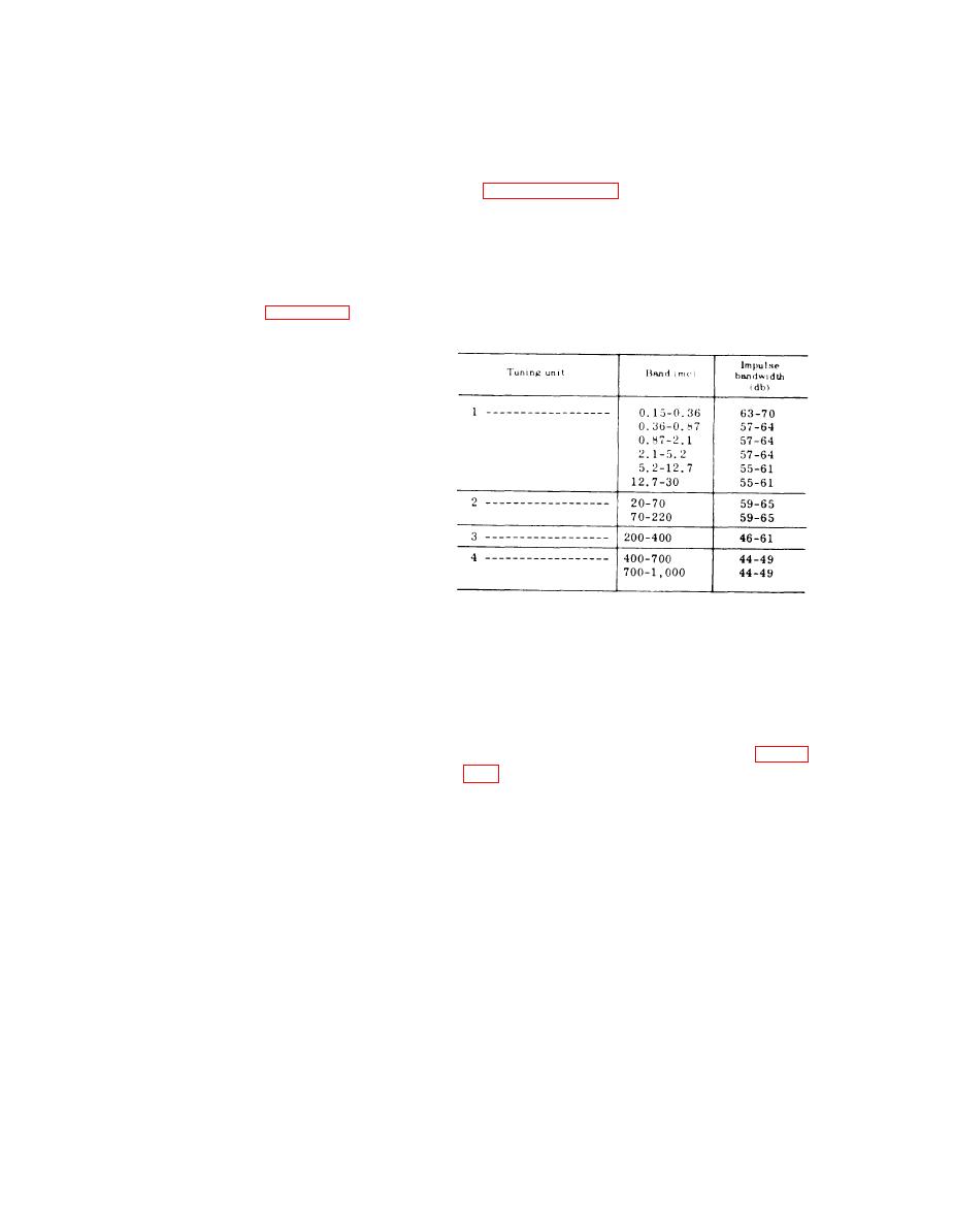 111. Bandwidth Determination
g e n e r a t o r output controls on cali-
bration charts 4A and 4B which are
To check the impulse bandwidth of the
located on pages 8 and 9 of the con-
t e s t set, compare the impulse bandwidth
d e n s e d plastic laminated operating
limits shown in the chart below with the
instructions supplied with each test
impulse generator output settings obtained
set, unless these settings are iden-
i n paragraph 110 above. The following
tical with those already shown.
chart indicates the impulse bandwidth
(8) Repeat the procedures given in (1)
l i m i t s . The settings recorded in the IM-
t h r o u g h (5) above for each fre-
P U L S E GENERATOR DB ABOVE lV/
quency shown on calibration charts
MC columns of calibration charts 4A and
4A and 4B.
4B of the condensed operating instructions,
b. If t u n i n g unit 4 is used, set up the
supplied with each test set, shall fall within
equipment as shown in figure 103 and pro-
impulse bandwidth limits in the chart
ceed as follows:
below.
(1) Set the READ-CALIBRATE switch
on the switching unit to READ and
adjust the output level of the tuning
u n i t 4 signal generator to obtain
an indication of 100,000 microvolt
on the power meter (See note in a
above.)
(2) Set the READ-CALIBRATE switch
o n the switching unit to CALI-
B R A T E , and the 20-db variable
step attenuator controls to 60 DB.
(3) Set the test set function switch to
CW AVERAGE and the calibration
s w i t c h to SERIES CAL & OPER-
ATE,
112. RF-IF. Attenuator Test
(4) S e t t h e S I G N A L A T T E N U A T O R
switch to 20 DB.
Connect the applicable tuning unit signal
generator, through the cable supplied with
(5) A d j u s t t h e G A I N c o n t r o l f o r a
it, or a 2-foot RG-5B/U coaxial cable
r e a d i n g of 20 db on the test set
terminated by two UG-18/U connectors, to
p a n e l meter.
the INPUT connector of the 20-db variable
(6) Set the test set function switch to
step attenuator (AT-106H) shown in figure
CW PEAK and the calibration
switch to SHUNT CAL.
v a r i a b l e step attenuator through a second
(7) Set the IMPULSE GENERATOR DB
R G - 5 B / U coaxial cable (as above) to the
ABOVE lV/MC switch to ON
SIGNAL INPUT jack on the test set.
a n d adjust the impulse generator
a . If the tuning unit is installed, pro-
output controls (coarse and fine) to
ceed as follows:
again obtain a reading of 20 db on
(1) S e t the 20-db variable step atten-
the test set panel meter.
u a t o r controls for an attenuation
(8) Record the settings of the impulse
of 80 DB and the test set SIGNAL
generator output controls on charts
ATTENUATOR switch to 0 CW
4A and 4B, unless the settings are
ONLY.
identical with those already shown.
(2) Adjust the output of the tuning unit
1 signal generator to obtain a
(9) Repeat the procedures given in (1)
reading of 10 microvolt at the test
t h r o u g h (8) above for each fre-
set SIGNAL INPUT jack.
quency shown (for tuning unit 4) on
(3) Set the test set GAIN control for a
c a l i b r a t i o n on charts 4A and 4B.
226
|
|
Privacy Statement - Press Release - Copyright Information. - Contact Us |
