 |
|||
|
|
|||
|
Page Title:
Calibration as Two-Terminal RF Voltmeter |
|
||
| ||||||||||
|
|  impulse g e n e r a t o r output level controls;
of the band under test; then check at two
t h e sum o f the settings is the reference
other equally spaced frequency points
--
within the band.
sensitivity.
k. Repeat the procedures in e through
j for each band of the tuning unit under test.
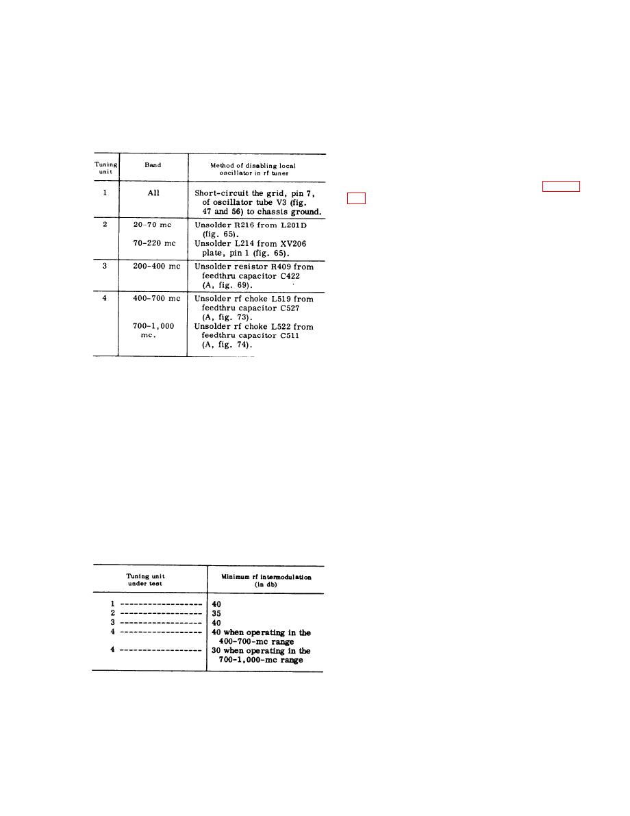
tuning unit under test. Each tuning unit re-
quires a different procedure for this oper-
110. Calibration as Two-Terminal RF
a t i o n . Perform the procedure outlined in
the following chart:
This procedure is used to calibrate. the
t e s t set as a two-terminal rf voltmeter.
S e t up the equipment as shown in figure
the 5-db variable step attenuator. The 10-
d b pad can be connected directly to the
tuning unit signal generator.
a. If tuning units 1, 2, or 3, are used,
c o n n e c t the applicable tuning unit signal
g e n e r a t o r (recently calibrated for power
o u t p u t ) to the test set and proceed as
follows:
(1) S e t t h e f u n c t i o n s w i t c h t o C W
A V E R A G E a n d the calibration
switch to SERIES CAL &OP-
ERATE.
(2) I f tuning unit 1 is used, set the
SIGNAL ATTENUATOR switch to
u n i t disabled (g above), readjust the im-
0 CW ONLY; if tuning units 2 or
p u l s e generator coarse and fine output
3 are used set the SIGNAL AT-
l e v e l control settings to again produce a
TENUATOR switch to 20 DB.
2-db indication on the panel meter. Record
(3) Set the tuning unit signal generator
t h e sum of the two output level control
output level to produce a 10-
s e t t i n g s : t h i s is the rf intermodulation
m i c r o v o l t signal at the SIGNAL
sensitivity.
INPUT terminal of the test set for
i. S u b t r a c t t h e v a l u e o f t h e r f i n t e r -
t u n i n g unit 1, or a 100 microvolt
modulation sensitivity (h above) from the
signal for tuning units 2 or 3.
r e f e r e n c e sensitivity (f above) to deter-
N o t e : If the 10-db pad is too large to
mine the difference in db. This difference
p r o v i d e a signal of proper amplitude at
in settings for the impulse generator out-
the test set SIGNAL INPUT terminal, use
p u t level controls must be the same or
a Pad of a smaller value (AT-50-8) to pro-
duce the proper signal amplitude.
h i g h e r than the values shown in the fol-
(4) Adjust the GAIN control to obtain
lowing chart:
a 20-db reading on the test set
p a n e l meter.
(5) S e t t h e f u n c t i o n s w i t c h t o C W
P E A K and the calibration switch
to SHUNT CAL.
(6) Set the IMPULSE GENERATOR DB
ABOVE lV/MC switch to ON
a n d adjust the impulse generator
output controls (coarse and fine) to
again obtain a 20-db reading on the
j. R e p e a t t h e p r o c e d u r e g i v e n i n e
t e s t set panel meter.
through i above for the high-frequency end
(7) Record the settings of the impulse
225
|
|
Privacy Statement - Press Release - Copyright Information. - Contact Us |
