 |
|||
|
|
|||
|
Page Title:
Alignment of Rf Tuner Section, Tuning Unit 1 |
|
||
| ||||||||||
|
|  Use the test harness (fig. 46). Each band
b. Disconnect plug P3, which is the input
of tuning unit 1 requires separate adjust-
plug to the 1,600-kc if. amplifier, from jack
ments. The adjustable e 1 e m e n t s are
J2 on the if. step attenuator (fig. 56 and
mounted on the cylindrical phenolic tuner
60) .
segments, Z1 through Z6 (fig. 58). Access
c. Connect plug P3 to the type 47250
to the tuning adjustments is obtained by
adapter at the output end of the tuning unit
inverting the tuning unit so that the three
1 signal generator coaxial cable. This
subminiature electron tubes, V1 through
step applies the output of the tuning unit 1
V3, are facing the repairman. Six access
signal generator to the input of the 1,600-kc
holes are located adjacent to the three
if. amplifier.
electron tubes. Use p h e n 01 i c alignment
d. Rotate the tuning unit GAIN control to
tools to adjust the variable coils and trim-
midposition.
mer capacitors. The powdered iron cores
e. Vary the output control of the tuning
for the coils are a d j u s t e d at the low-
unit 1 signal generator so that an onscale
frequency end of each band; the ceramic
indication can be seen on the panel meter
trimmer capacitor is adjusted at the high-
of the main unit.
frequency end.
1,600-kc if. amplifier is mounted in an up-
b. Inject the unmodulated rf output of the
right position on the tuning unit. Invert the
tuning unit 1 s i g n a 1 generator into the
tuning unit. Adjust the variable cores at the
front-panel S I G N A L INPUT jack as
bottom of if. transformers T25, T26, T27.
follows:
and T28, in this sequence, to obtain a
(1) T e r m i n a t e the attenuator output
maximum indication on the front-panel
connector on the tuning unit 1 sig-
meter.
nal generator with the type 1000-
g. Place the tuning unit in its upright
P2 40-ohm series unit (supplied as
position. Adjust the variable cores at the
an accessory with the tuning unit 1
tops of if. transformers T24 through T27,
signal generator).
in this sequence, to obtain maximum out-
(2) Connect the type 874-R22 coaxial
put .
c a b l e (supplied as an accessory
h. Repeat the procedures given in f a n d
with the tuning unit 1 signal gen-
g above for final peak adjustments.
erator) to the output end of the 40-
i. Disconnect plug P3 from the type
ohm termination.
47250 and reconnect P3 to jack J2 on the
(3) U s e t h e U G - 2 0 1 A / U N - s e r i e s
if. step attenuator.
adapter to mate the B NC connector
(at the output of the tuning unit 1
87. Alignment of Rf Tuner Section,
signal generator cable) to the N-
Tuning Unit 1
type SIGNAL INPUT jack on the
main unit.
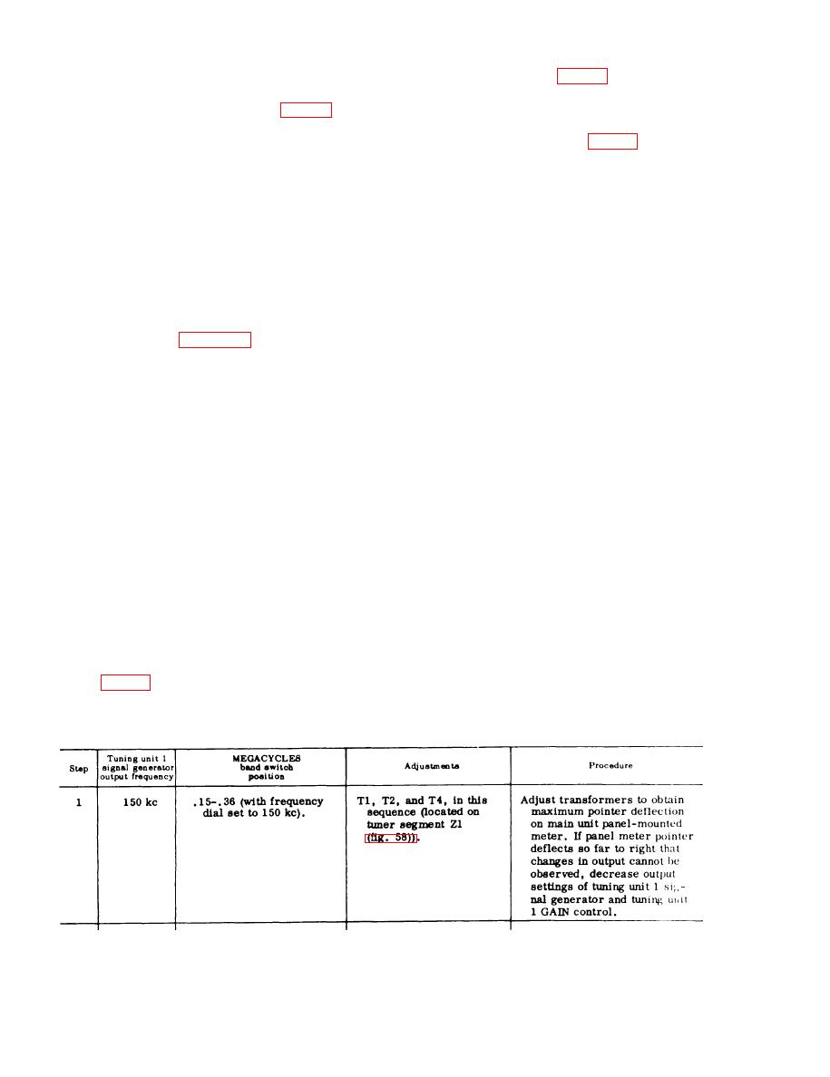
c. Proceed as directed in the following
a. To align the rf tuner, the tuning unit
chart.
must be operated outside of the main unit.
194
|
|
Privacy Statement - Press Release - Copyright Information. - Contact Us |
