 |
|||
|
|
|||
|
Page Title:
Disassembly Procedure for Six-Step Signal Attenuator AT702 |
|
||
| ||||||||||
|
|  (14) and bushing (15). Slide the rear
are precision 1 percent tolerance parts. In addi-
tion, resistors R709, R710, R716, R722, R723, and
m o v a b l e plate with attached con-
R724, which are mounted on function switch S702
nector J718 (13) off the two sleeve
s p a c e r s (53) and attenuator shaft
Also, resistors R713 and R714, which are mounted
(56).
on terminal board TB705 (fig. 43) have 1 percent
tolerance. If these parts require replacement, use
Disconnect the front movable plate
(3)
the exact value of the part removed. If even slightly
( 2 0 ) from the connecting link rod
different values are used, the accuracy of the test
( 1 9 ) by r e moving the machine
set wll be affected.
screw (17) and bushing (18).
a. Disassembly Procedure for Six-Step
Loosen the two setscrews (48) that
(4)
secure the guide (49) to one of the
I f the source of malfunctioning has been
s l e e v e spacers (53). Remove the
guide.
localized to six-step signal attenuator
L o o s e n two setscrews (23) on the
A T 7 0 2 (para 67c(2)), disassemble the at-
(5)
b r i d g e (24), and slide the bridge
tenuator by referring to figure 90 and then
and barrel assembly (34) off the two
follow the procedures given in (1) through
s l e e v e spacers (53) and attenuator
(6) below.
shaft (56) .
(1) R e m o v e the three machine screws
( 1 ) and lockwashers (2) from the
T o remove a fixed attenuator (38
(6)
r e a r fixed plate (3). Remove the
through 43) from the barrel assem-
bly (34), stand the barrel assembly
rear fixed plate with attaching parts
on its end. R e m o v e the three
(4 through 10).
(2) Disconnect the rear moveable plate
machine screws (35) and lock-
( 1 1 ) from the connecting link rod
washers (36) from the locating ring
(16) by removing the machine screw
(37), and lift the locating ring off
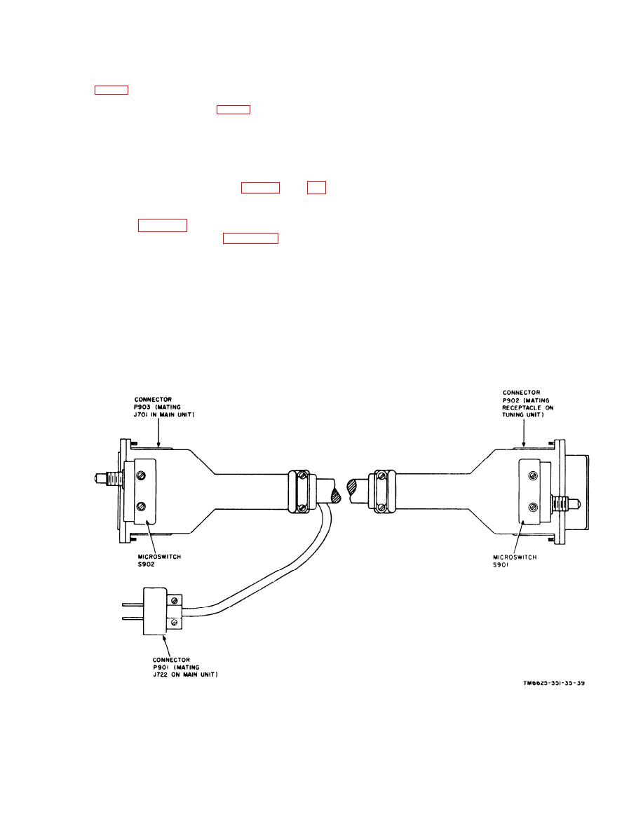
Figure 88. Cable Assembly, Special Purpose, Eledtrical Branched CX-6681/URM-85,
p a r t s location diagram.
183
|
|
Privacy Statement - Press Release - Copyright Information. - Contact Us |
