 |
|||
|
|
|||
|
Page Title:
Figure 86. Couplers, A n t e n n a CU-893/URM-86 and CU-894/URM-85, parts location diagram. |
|
||
| ||||||||||
|
| 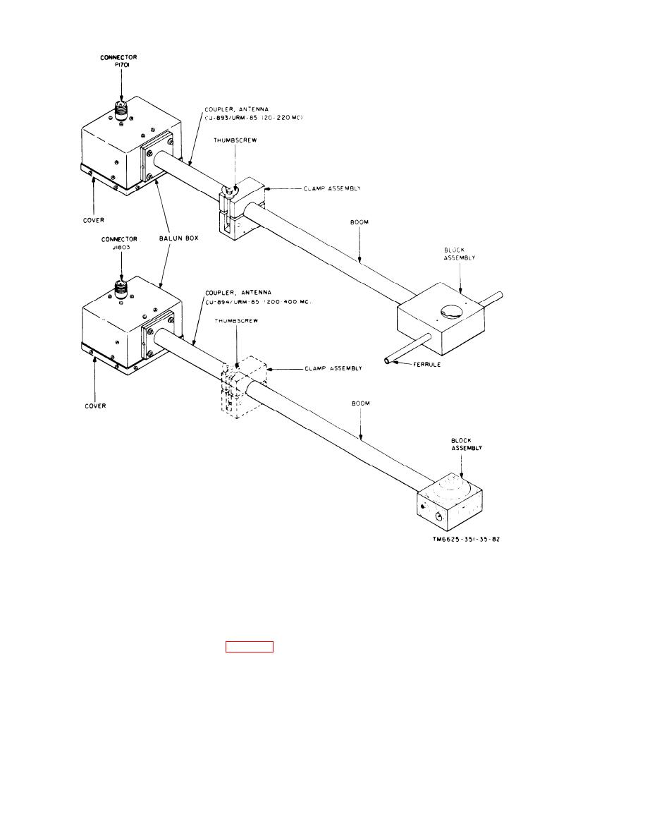 Figure 86. Couplers, A n t e n n a CU-893/URM-86 and CU-894/URM-85, parts location diagram.
block and c o n n e c t o r P1601 at
11-6625-351-12. After it is established
the base of the AS-l158/URM-
that the source of possible trouble in the
85.
main unit and in the tuning unit (para 74)
(2) If the check in (1) above does not
h a s been eliminated, check for possible
remedy the trouble, disconnect the
troubles within these two minor com-
unbalanced injection block from the
ponents a8 follows:
AS-1158/URM-85 and use an ohm-
(1) D e f e c t i v e connection between
m e t e r to check for continui,ty as
n o n c o l o r - c o d e d connector J2002
follows:
on the u n b a l a n c e d injection
178
|
|
Privacy Statement - Press Release - Copyright Information. - Contact Us |
