 |
|||
|
|
|||
|
Page Title:
Chapter 3. REPAIRS AND ALIGNMENT |
|
||
| ||||||||||
|
|  CHAPTER 3
REPAIRS AND ALIGNMENT
Section I. REPAIRS
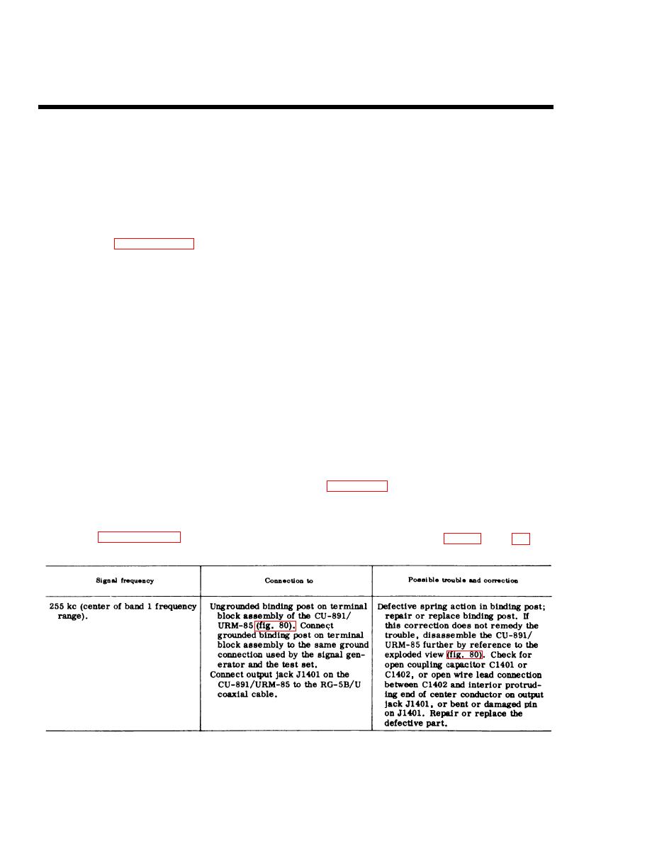
only band 1 of the MEGACYCLES switch
76. Replacement of Parts, Minor
( . 1 5 - . 3 6 ) mc position. Apply the signal
Components for Use with Tuning
t h a t is indicated in the signal frequency
Unit 1
column of the charts in b below. Monitor
a. General. After completing the tests
t h e final output by observing an onscale
indication on the main unit panel meter. If
o u t l i n e d in paragraph 71, the signal sub-
n e c e s s a r y , rotate the SIGNAL ATTENU-
stitution technique can be used for
ATOR DB control to higher or lower steps
determining whether parts within the minor
than its initially recommended 20-db step
c o m p o n e n t s supplied for use with tuning
p o s i t i o n so that the relative amplitude of
unit 1 require repair or replacement.
t h e test signal can be observed on the
These tests are performed with tuning unit
meter. A second method of monitoring the
1 installed in the tuning unit compartment
final output can be obtained by connecting
of the main unit. The following procedures
the headset, through the headset cord, into
are based on the assumption that sources
t h e main unit front-panel PHONES jack.
of trouble in both tuning unit 1 and the main
I f the signal source is modulated at an
u n i t have been eliminated, and that there
audio frequent y rate and an audio note is
i s no need for operating tuning unit 1,
not heard in the headset, trouble is indi-
t h r o u g h the test harness, outside of the
main unit. The following checks are to be
c a t i d . Isolate the trouble as indicated in
t h e Possible trouble and correction col-
made with tuning unit 1 installed in the main
umn of the following charts, and repair or
unit tuning unit compartment. In all tests,
r e p l a c e the defective part or parts. Con-
a cable assembly, consisting of a 3-foot
n e c t tuning unit 1 signal generator, m@-
l e n g t h of RG-5B/U coaxial cable termi-
lated at 400 cps, to the test set as shown
n a t e d by UG-18/U connectors, is used to
i n figure 79, and follow the procedures
c o u p l e the test signal from the output of
given in b below.
the minor component under test to the main
u n i t front-panel SIGNAL INPUT jack
b. Coupler, Radio Frequency Interfer-
( J 7 0 5 ) . Set the front-panel controls as
l i s t e d in paragraph 71a, except for using
166
|
|
Privacy Statement - Press Release - Copyright Information. - Contact Us |
